Hem / VW Wiring Diagrams
VW Wiring Diagrams
http://www.volkspower.nl/tech/wiring/http://www.volkspower.nl/tech/wiring/
Also available:
- DIN Terminal Designations - a table of what those numbers on electrical parts mean!
- DIN Terminal Cross Reference - a table of old to new terminal designations
- Electrical accessory power consumption - how much power different components draw
Click on a dot to download the diagram
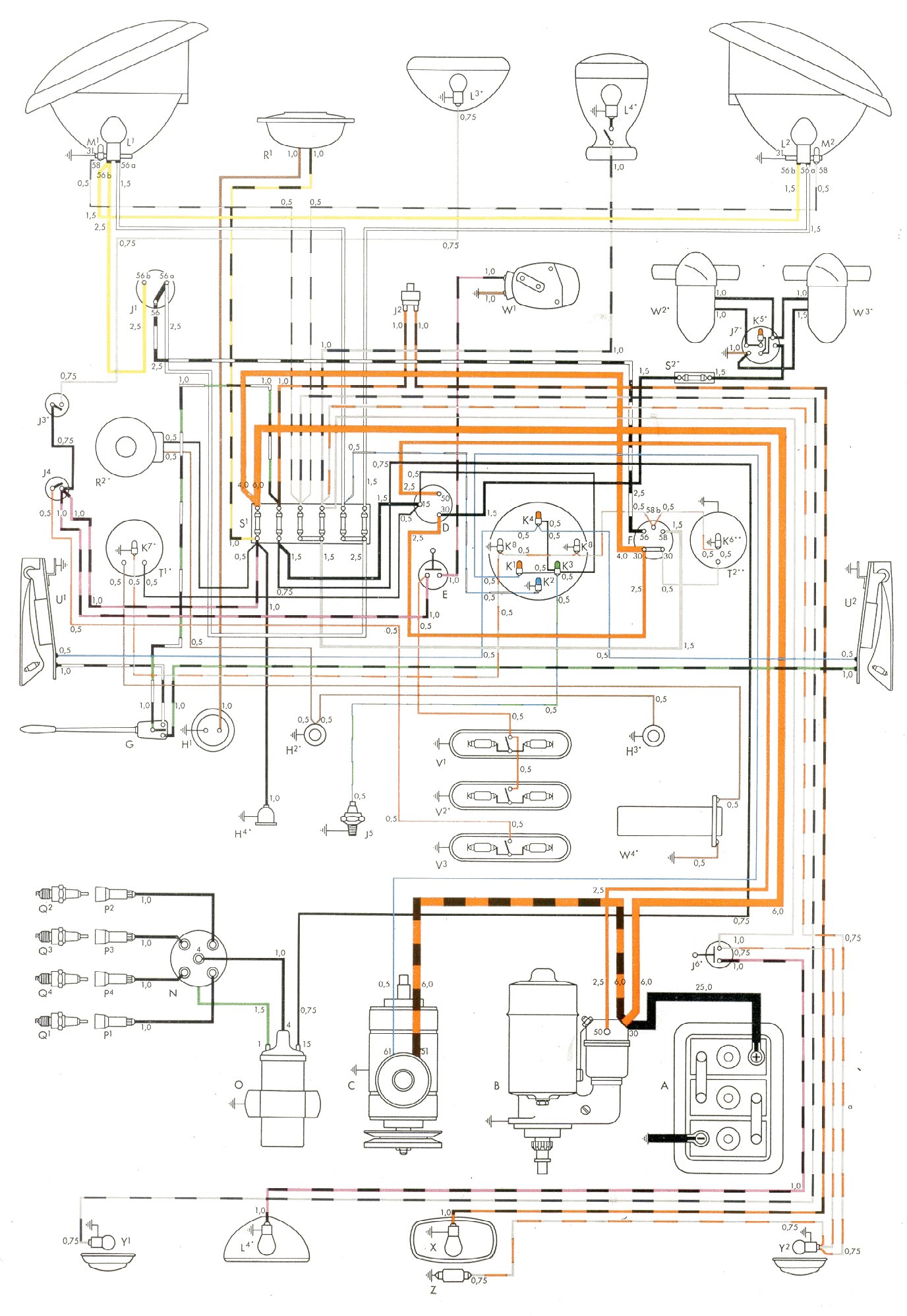
Bus
| Year | Comment |
Key
|
Fuse Block
|
Diagram
|
|---|---|---|---|---|
| 1950-1953 | Barndoor |
 |
 |
 |
| 1954-1955 | to 3/55 |
 |
 |
 |
| 1955-1956 | from 3/55, Non-USA |
 |
|
 |
| 1956-1961 | Non-USA |
 |
|
 |
| 1956-1961 | USA |
|
|
 |
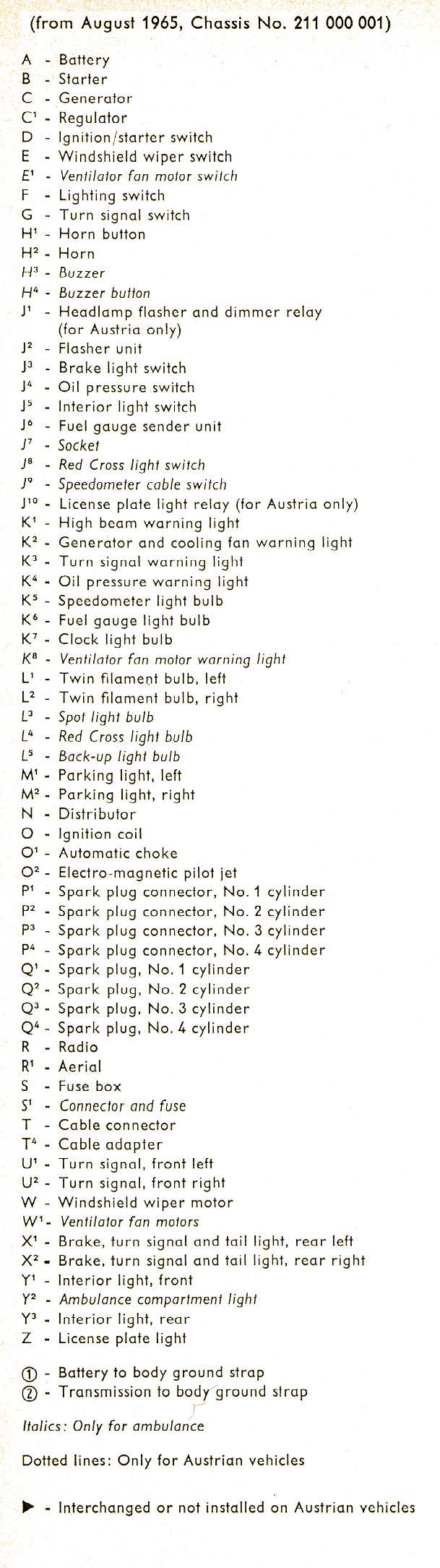
| 1962-1965 | Non-USA |
 |
 |
 |
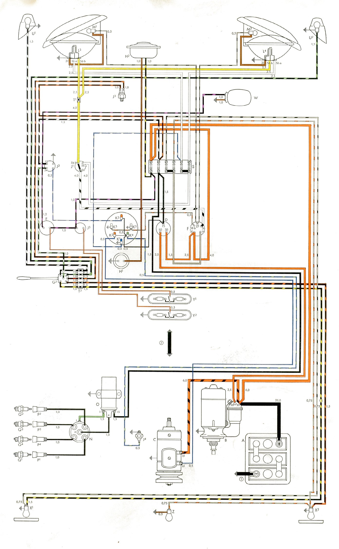
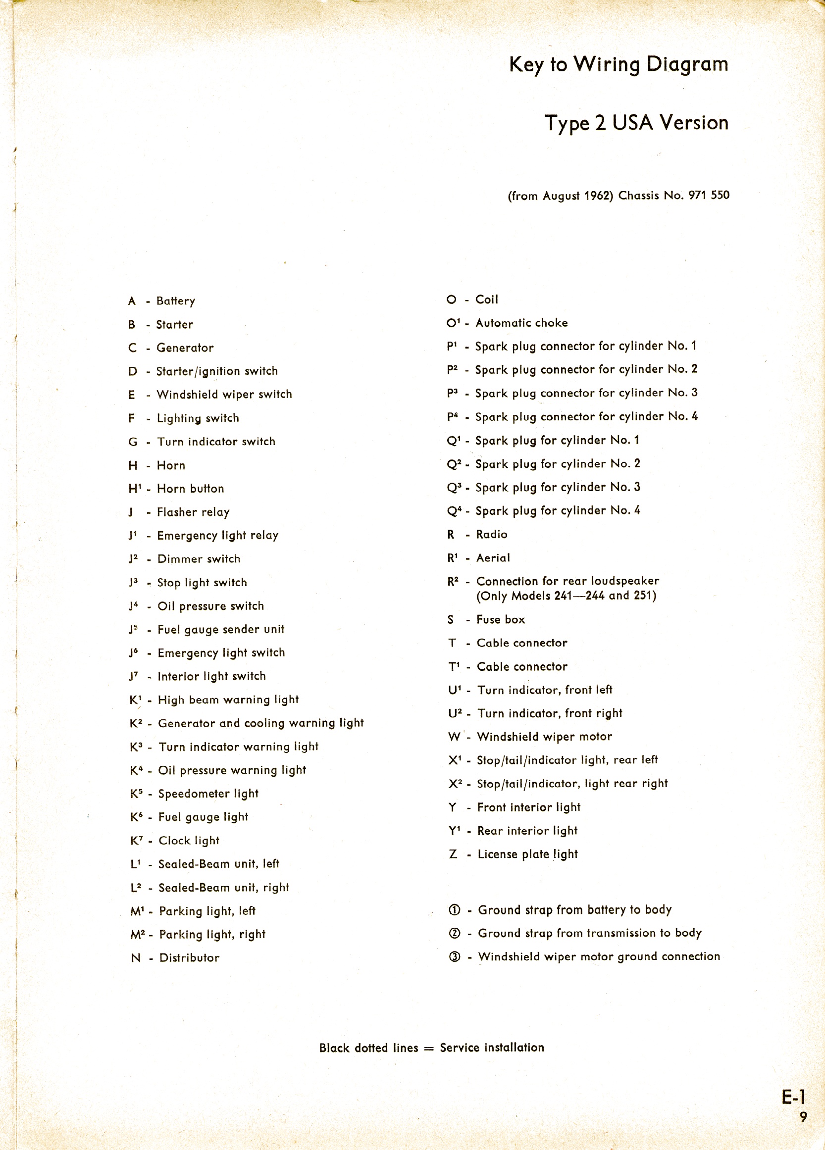
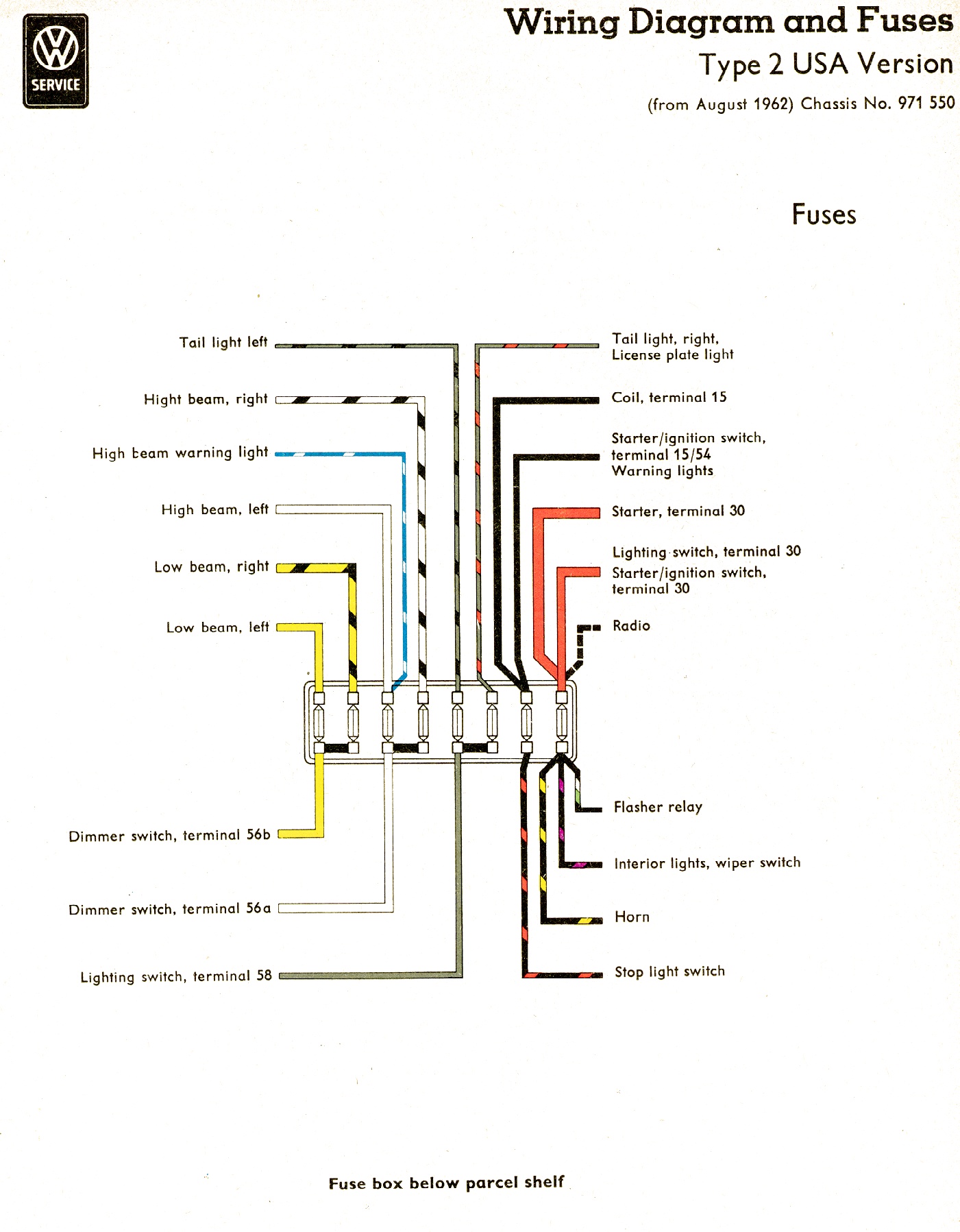
| 1962-1965 | USA |
 |
 |
 |
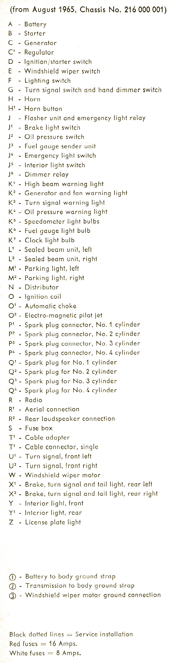
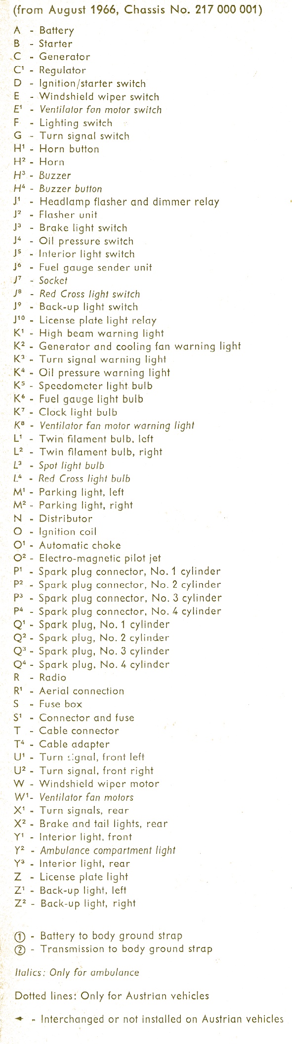
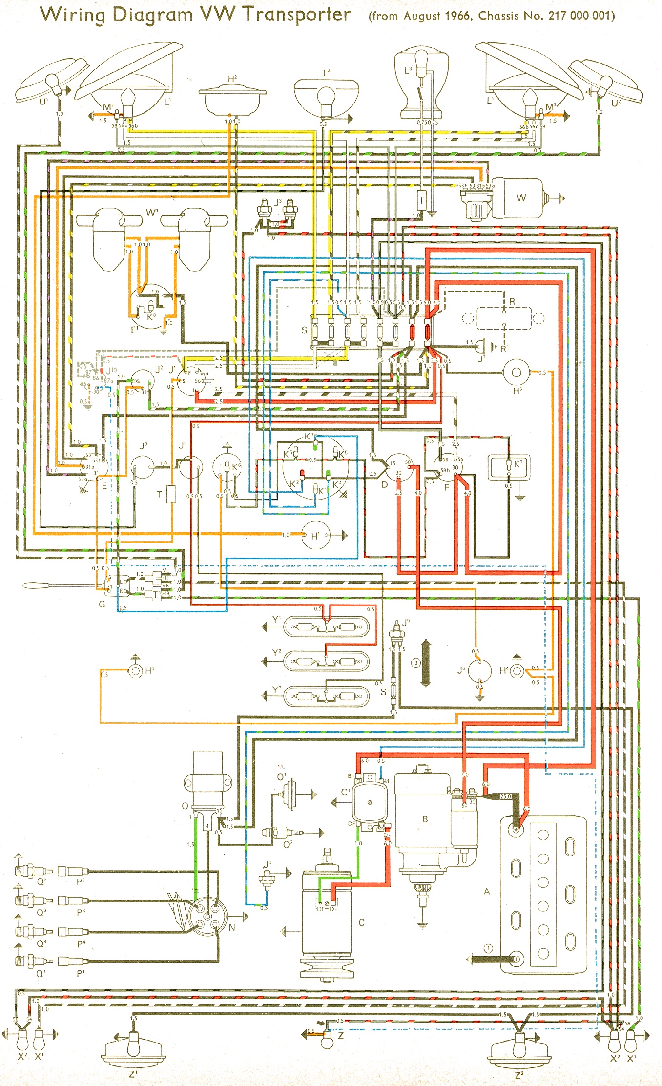
| 1966 | Non-USA |
 |
|
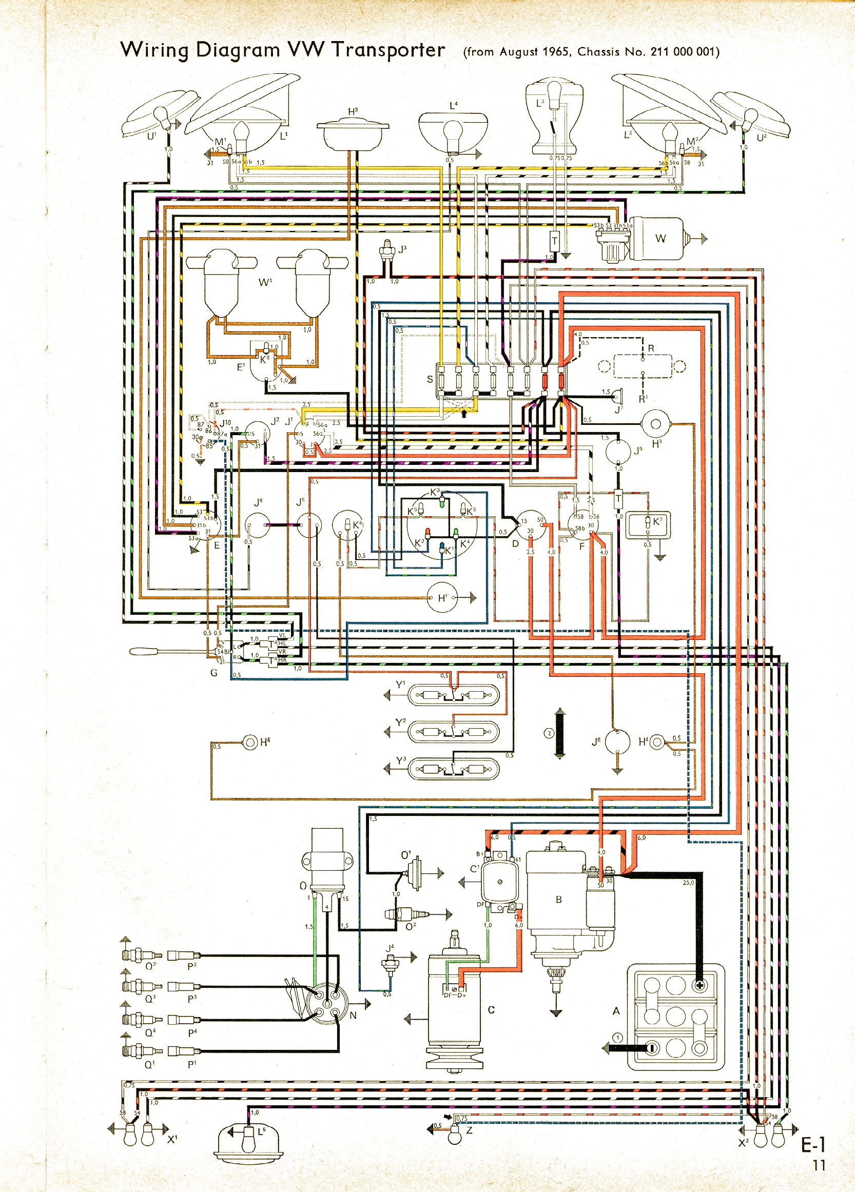 |
| 1966 | USA |
 |
|
 |
| 1967 | Non-USA |
 |
|
 |
| 1967 | USA |
 |
|
 |
| 1968-1969 |
|
|
 |
|
| 1968 | Non-USA |
|
|
|
| 1968 | USA |
|
|
|
| 1969-1970 |
|
|
 |
|
| 1970-1971 |
|
|
 |
|
| 1970 | Non-USA |
|
|
|
| 1970 | USA |
|
|
|
| 1971-1972 |
|
|
 |
|
| 1971 | Non-USA |
|
|
|
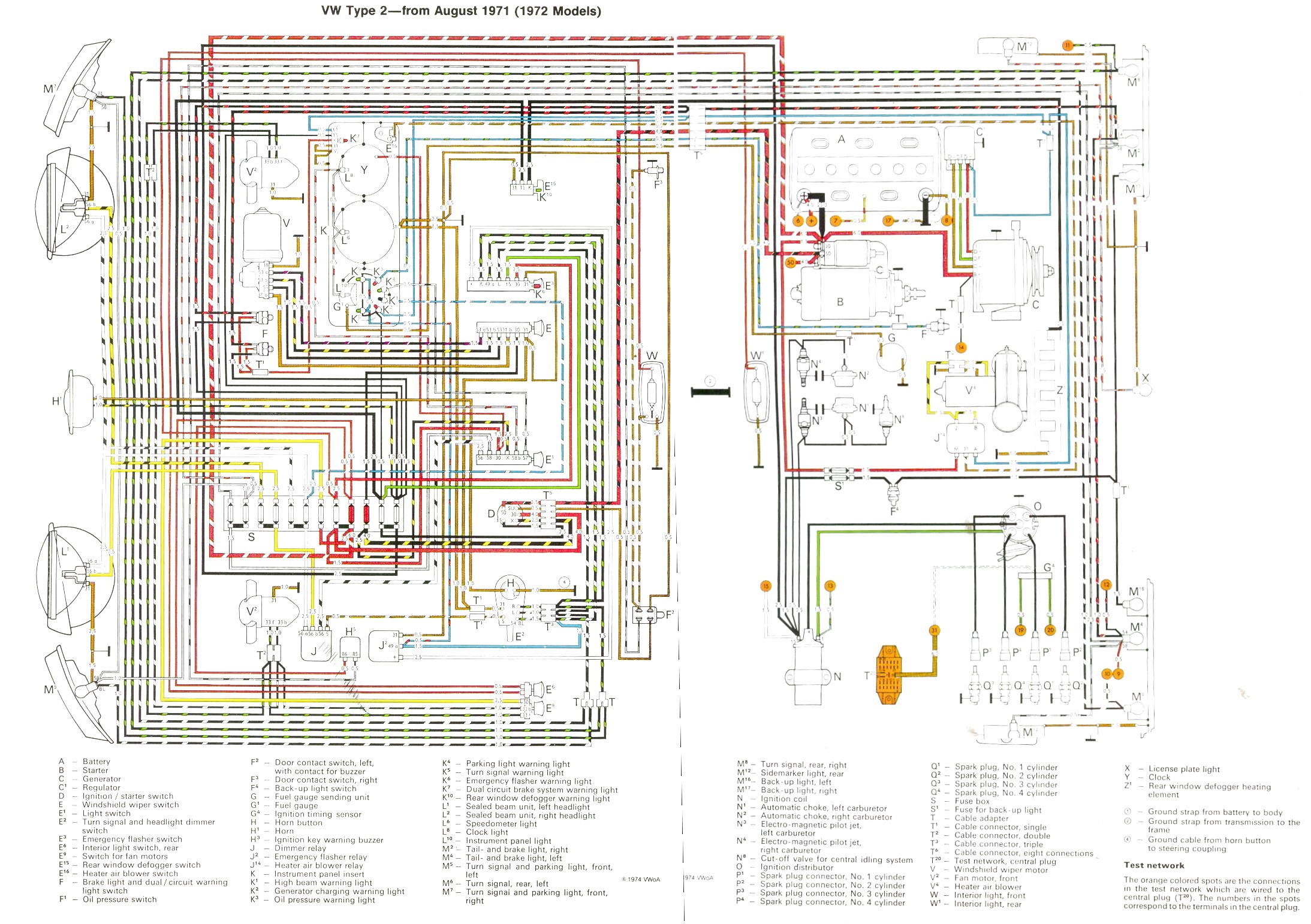
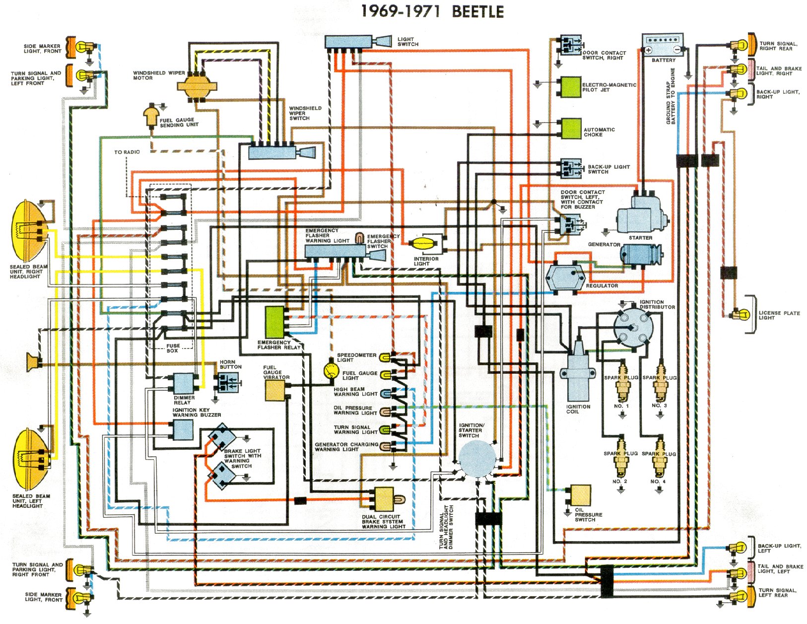
| 1971 | USA from August 1970 | |||
| 1971 | USA from January 1971 | |||
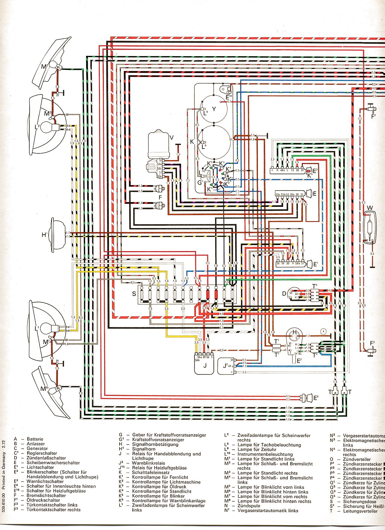
| 1972 | Non-USA | |||
| 1972 | USA | |||
| 1972 | 1700 | |||
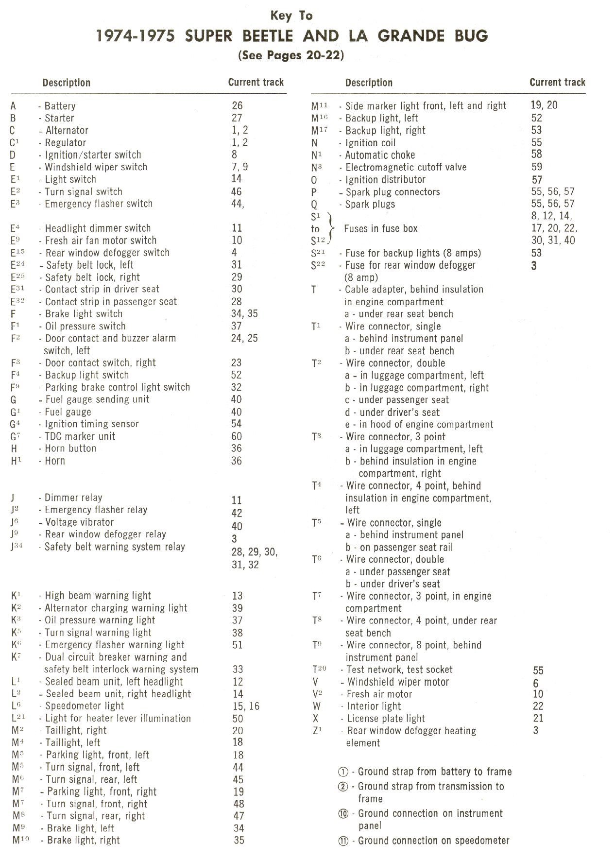
| 1973-1975 |
|
|
 |
|
| 1973 | ||||
| 1973 | 1700 | |||
| 1973 | USA | |||
| 1974 | 1800 | |||
| 1974 | USA | |||
| 1976 |
Key 1 goes on left side of diagram Key 2 goes on right side of diagram |
|
 |
|
| 1977 |
Key 1 goes on bottom of diagram Key 2 goes on right side of diagram |
|
 |
|
| 1978 - 1979 |
|
|
||
| 1979 | Westfalia Accessories |
|
|
 |
| 1990 - 1991 | Vanagon |
|
 1
1 2
2 1
1 2
2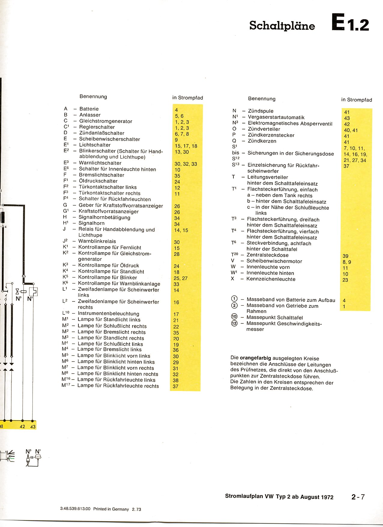 3
3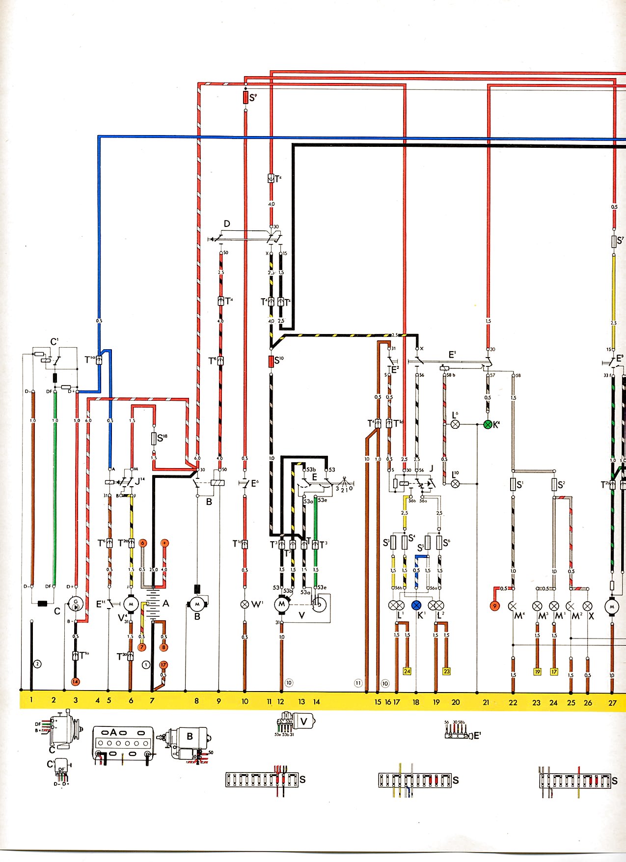 1
1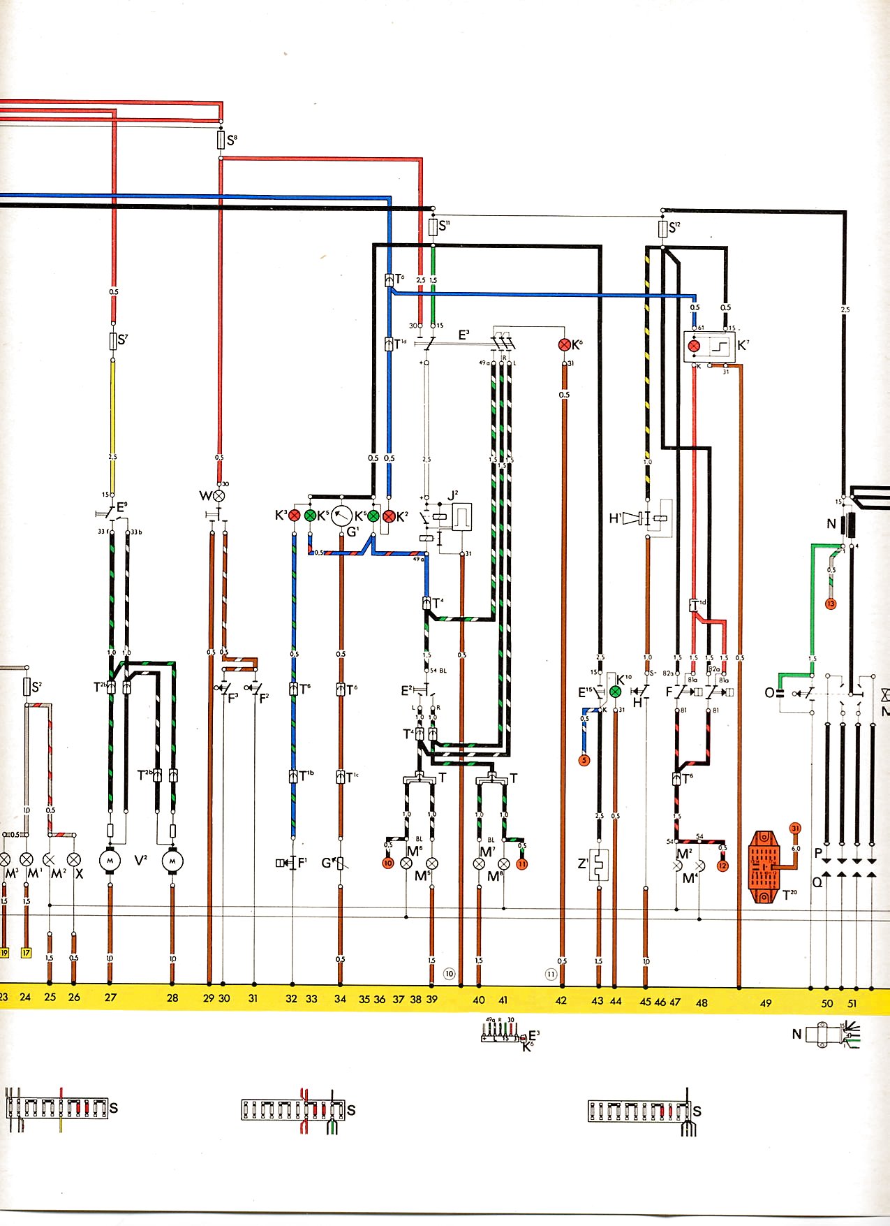 2
2 3
3 4
4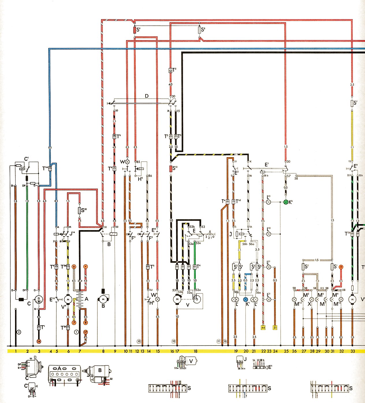 1
1 2
2 3
3 1
1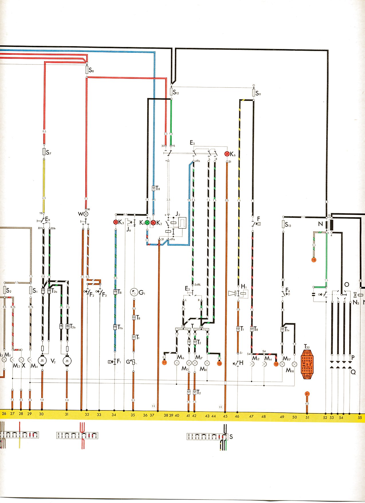 2
2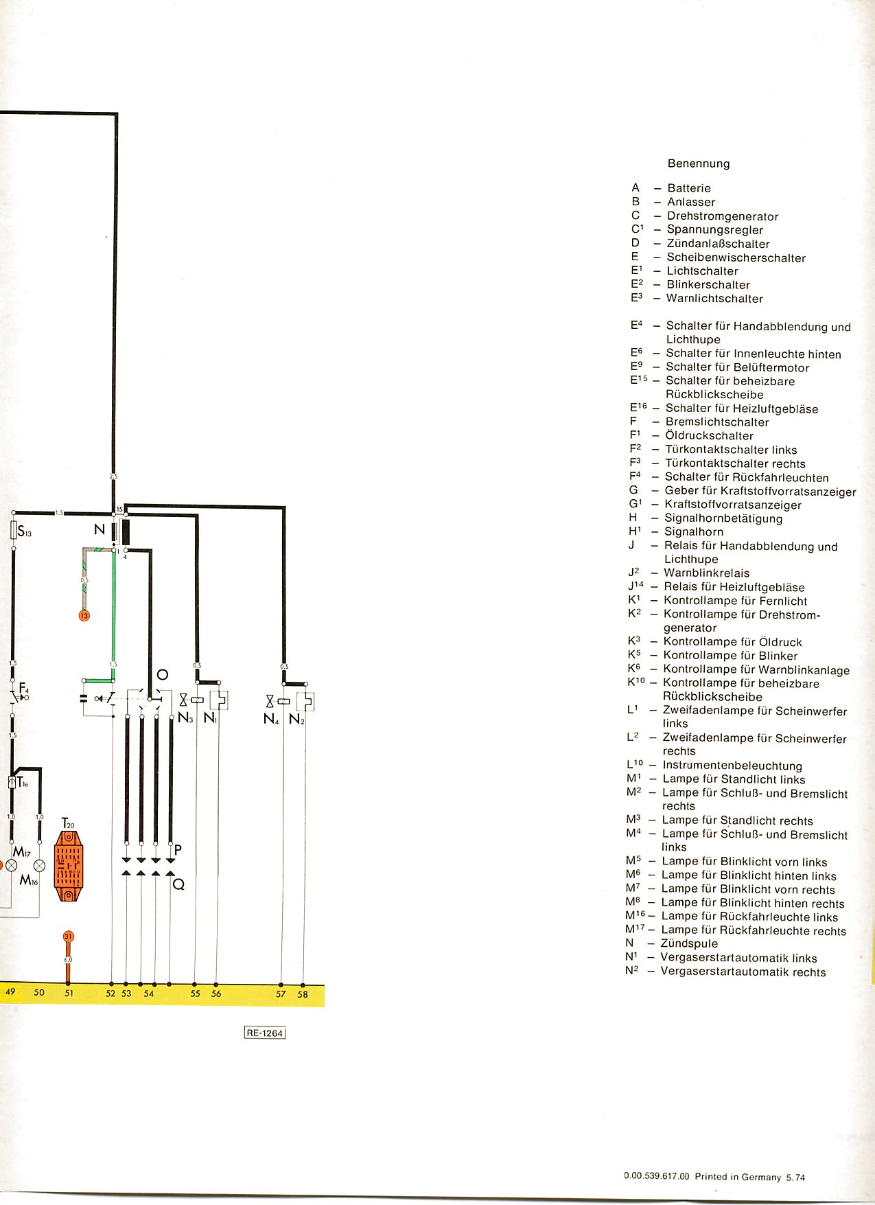 3
3 4
4 1
1 2
2 3
3 4
4 1
1 2
2 1
1 2
2 1
1 2
2 3
3 1
1 2
2 1
1 2
2 3
3 4
4 5
5 6
6 7
7 8
8 10
10 11
11 12
12 13
13 14
14 15
15
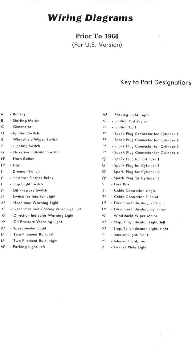
Beetle
| Year | Comment |
Key
|
Fuse Block
|
Diagram
|
|---|---|---|---|---|
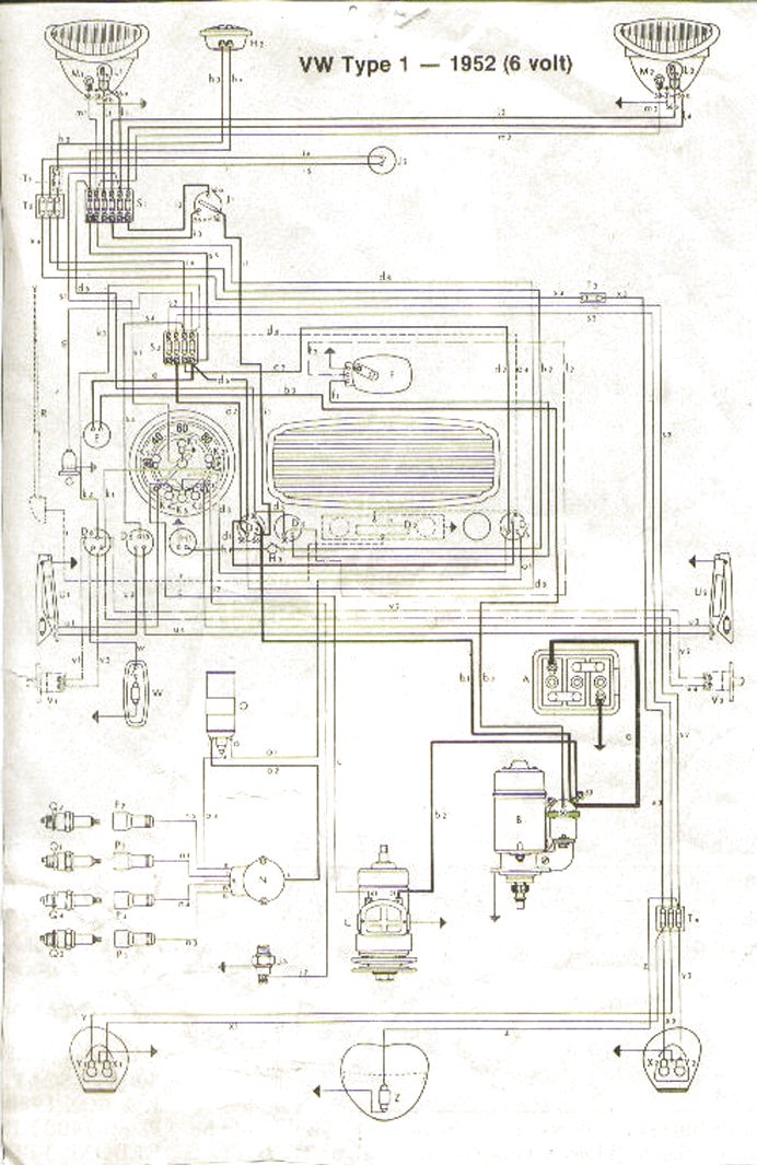
| 1952-1953 |
|
|
 |
|
| 1954 |
|
|
 |
|
| 1955-1957 |
 |
|
 |
|
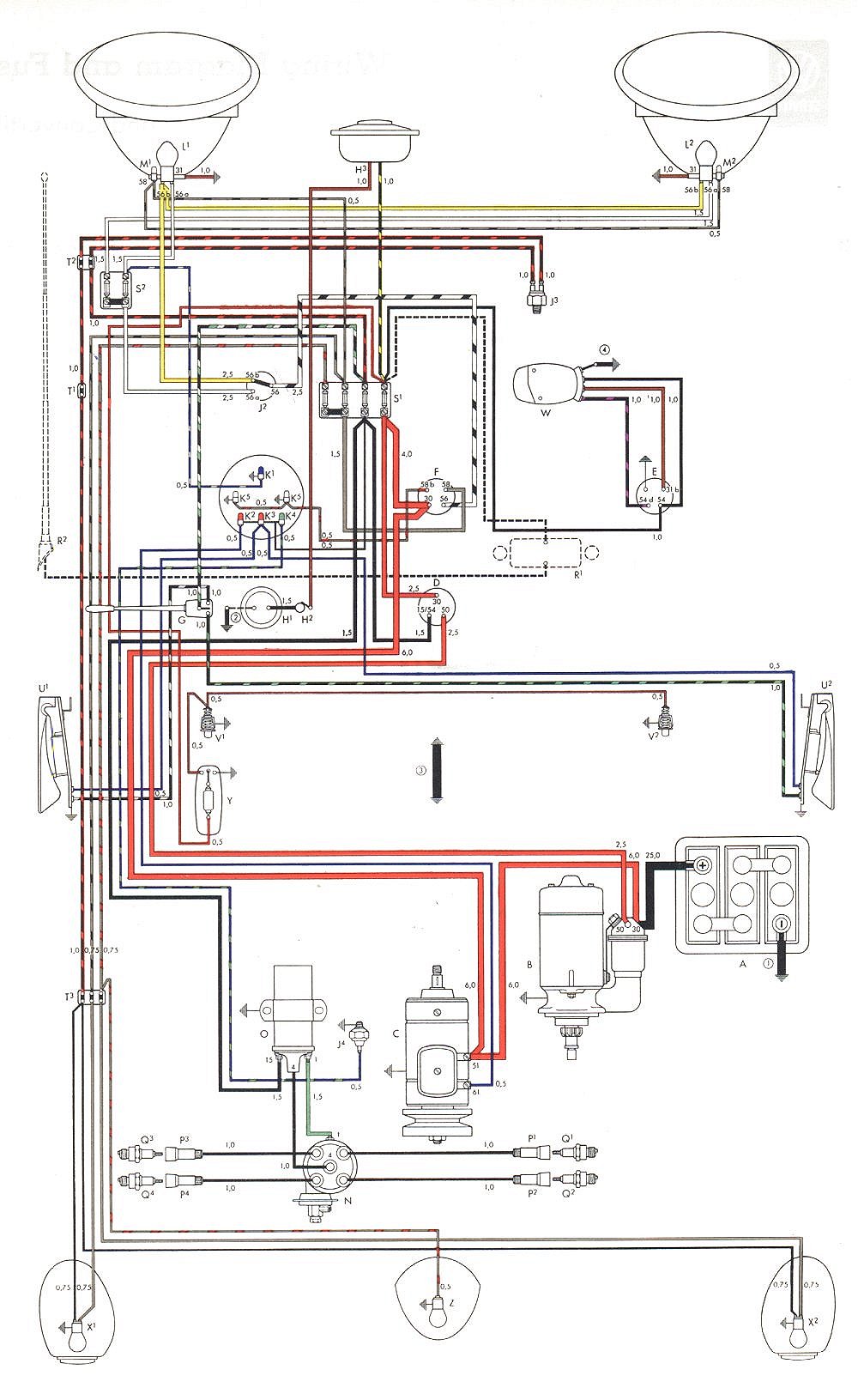
| 1958-1959 | Non-USA |
 |
|
 |
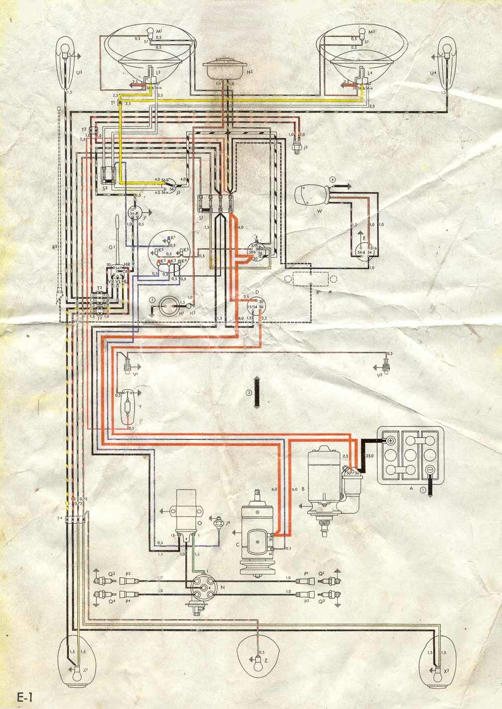
| 1958-1959 | USA |
 |
|
 |
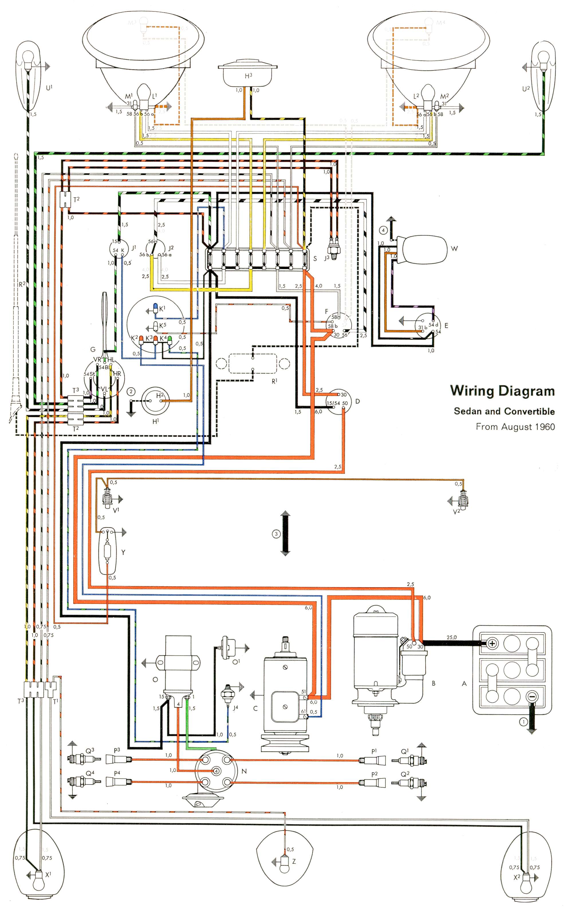
| 1960-1961 |
 |
 |
 |
|
| 1960-1961 | Australia |
|
|
 |
| 1962-1965 |
 |
 |
 |
|
| 1966 |
|
|
 |
|
| 1966-1967 |
|
|
 |
|
| 1967-1970 | Australia |
|
|
 |
| 1968-1969 |
|
|
 |
|
| 1969-1971 |
|
|
 |
|
| 1970 | 1600 USA |
|
|
|
| 1971 | 1302 with test central socket |
|
|
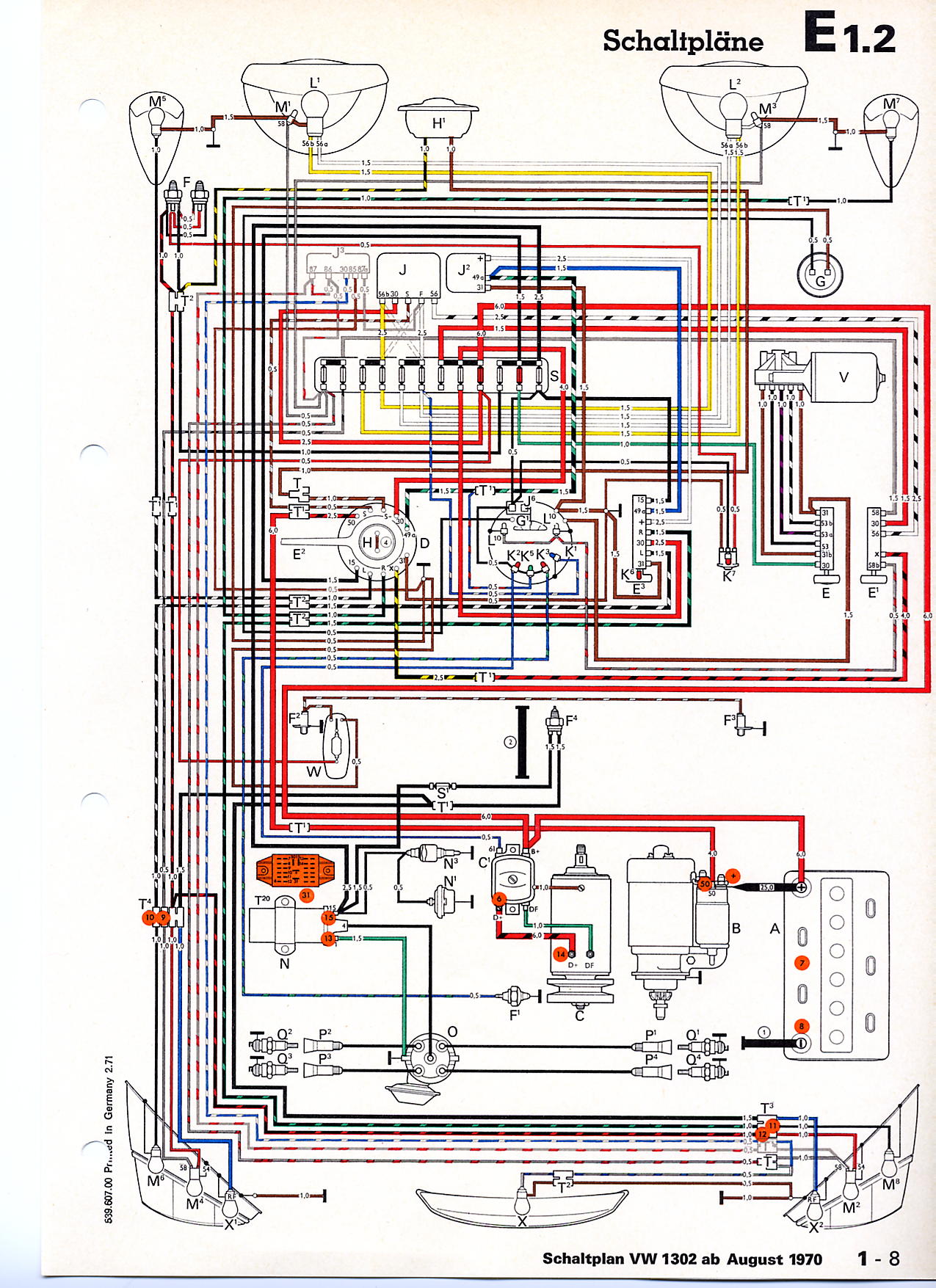 |
| 1971 | 1302 without test central socket |
|
|
 |
| 1971 | 1302 Additional items |
|
|
 |
| 1971 | 1302 USA |
|
|
 |
| 1971 | 1302 USA Additional items |
|
|
 |
| 1970-1971 | Supplements |
|
|
 |
| 1971 | Super Beetle |
|
 |
 |
| 1972 | 1300 and 1302 USA |
|
|
|
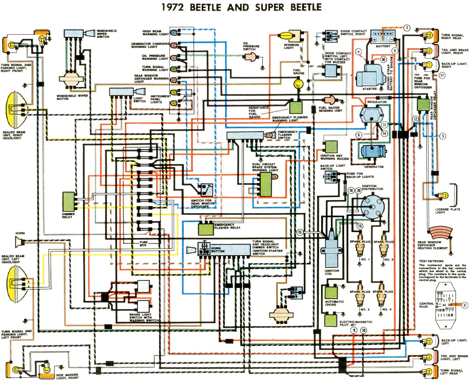
| 1972 | Beetle and Super Beetle |
|
|
 |
| 1972 | Supplement |
|
|
 |
| 1972? | Chassis wire routing |
|
|
 |
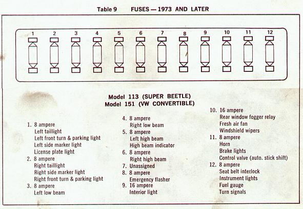
| 1973 | How to read 73+ diagrams |
|
 |
 |
| 1973 | 1200 |
|
|
|
| 1973 | 1300 and 1303 |
|
|
|
| 1973 | 1300 USA |
|
|
|
| 1973 | 1303 USA |
|
|
|
| 1973 | Super Beetle |
 |
|
|
| 1974 | 1303 |
|
|
|
| 1974 | 1303 USA |
|
|
|
| 1974-1979 |
 |
|
 1
1 2
2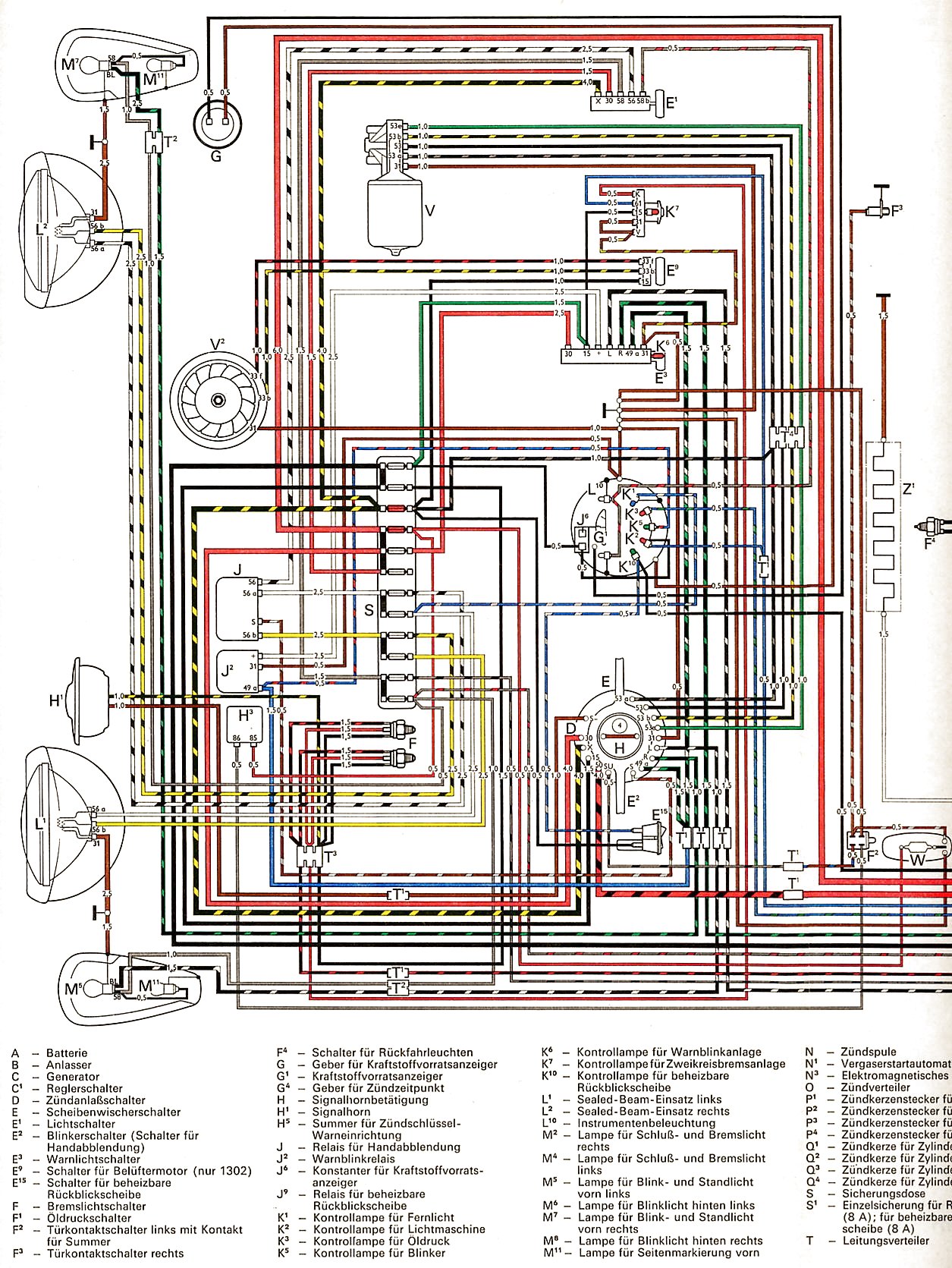 1
1 2
2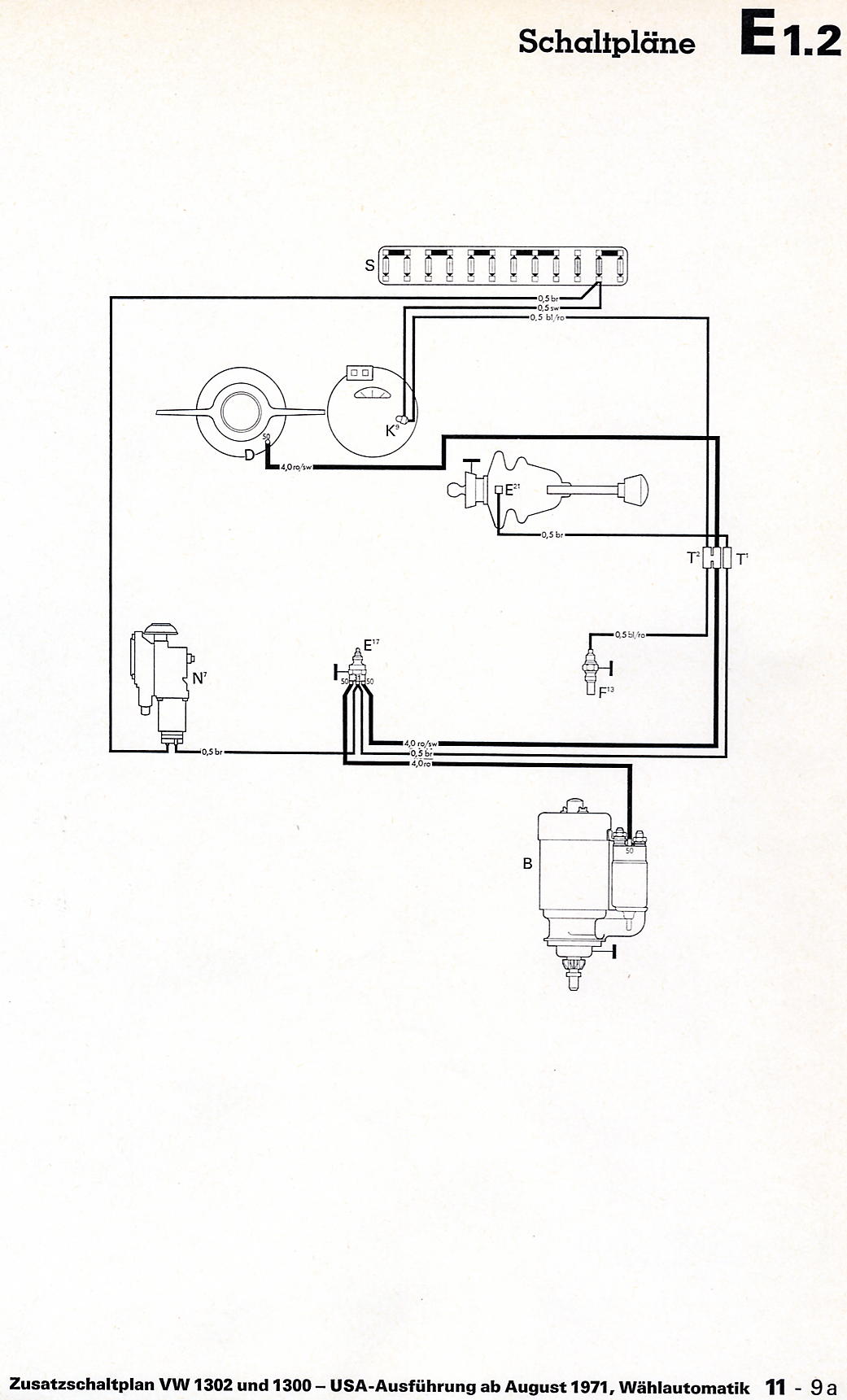 3
3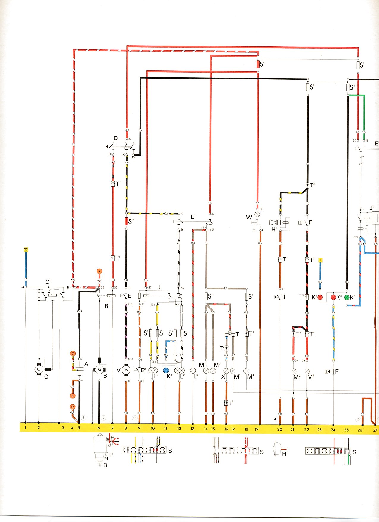 1
1 2
2 3
3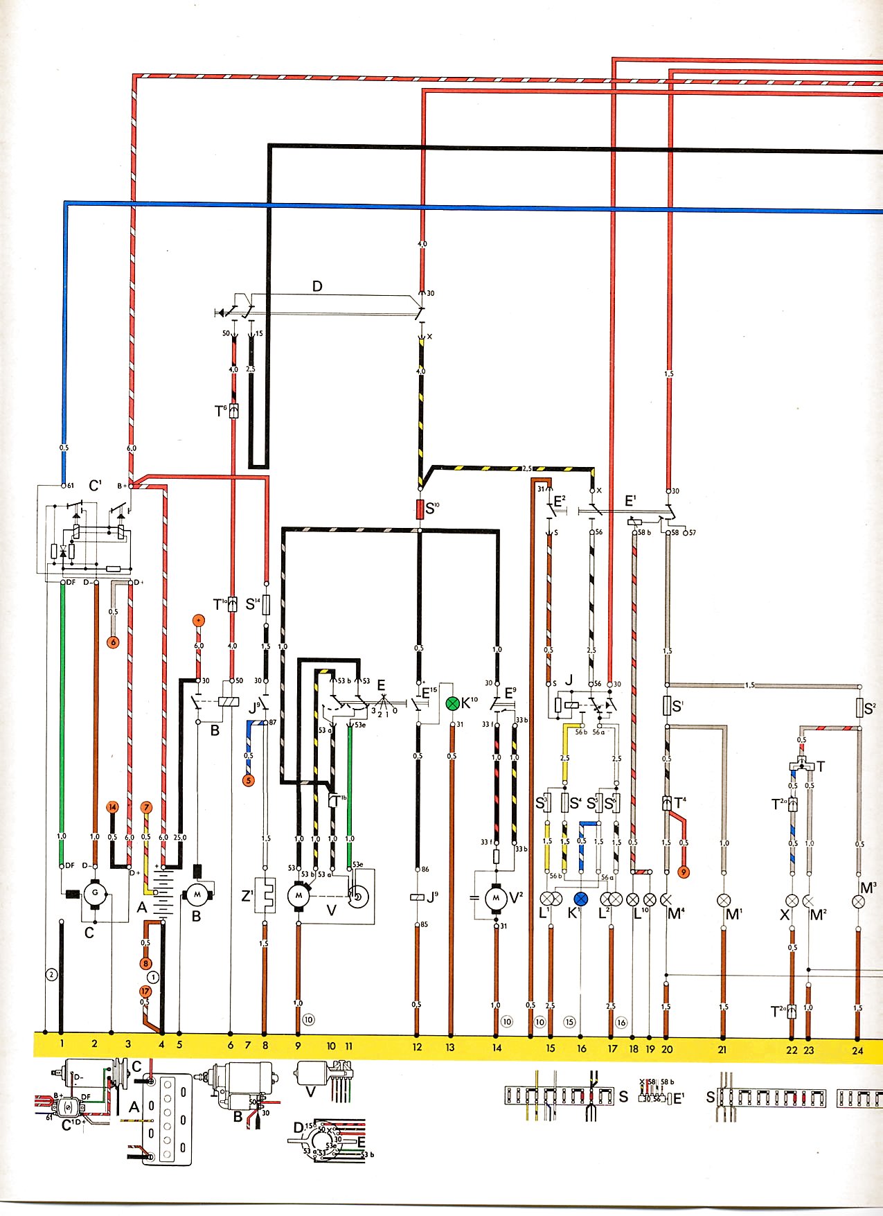 1
1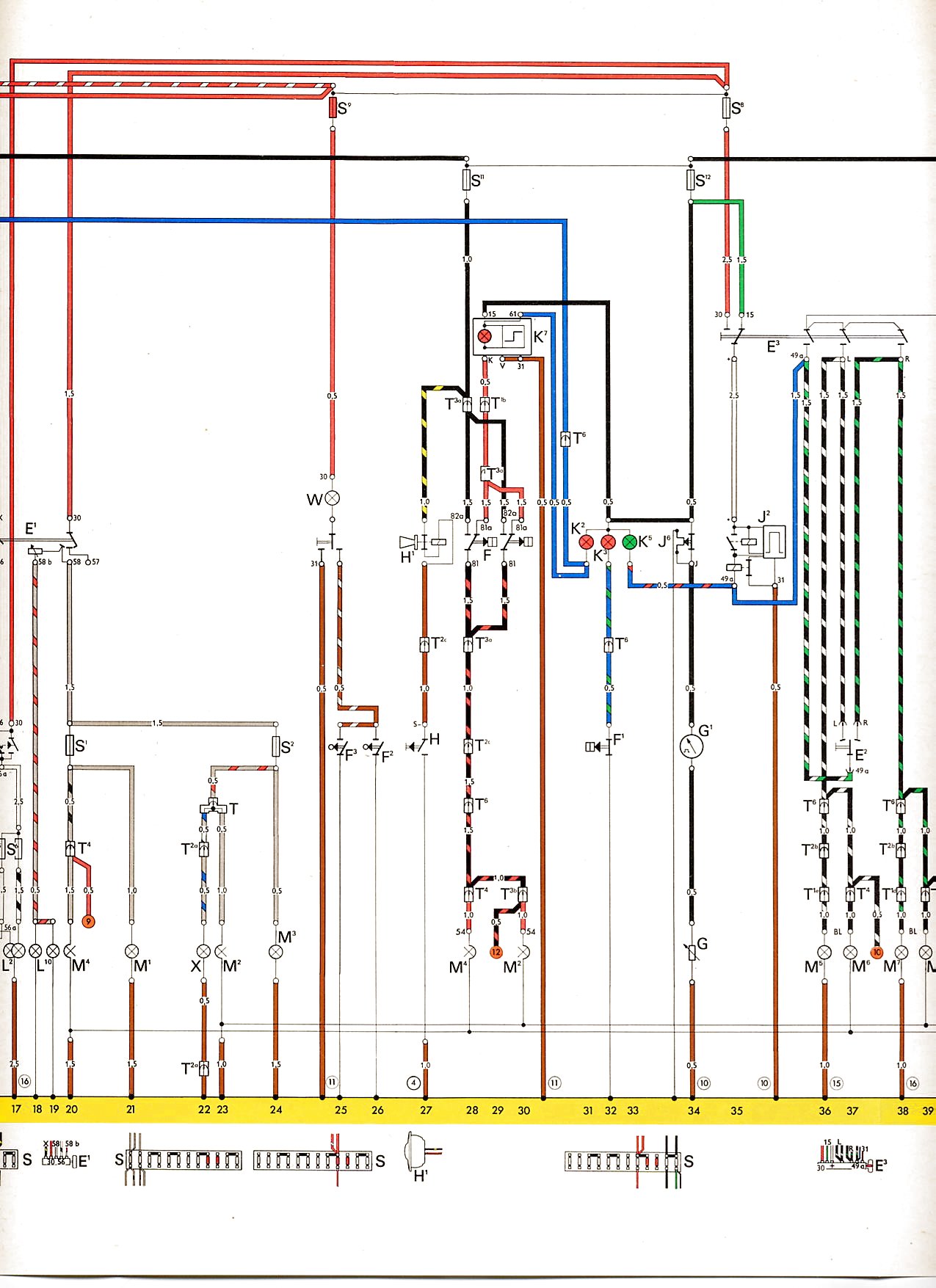 2
2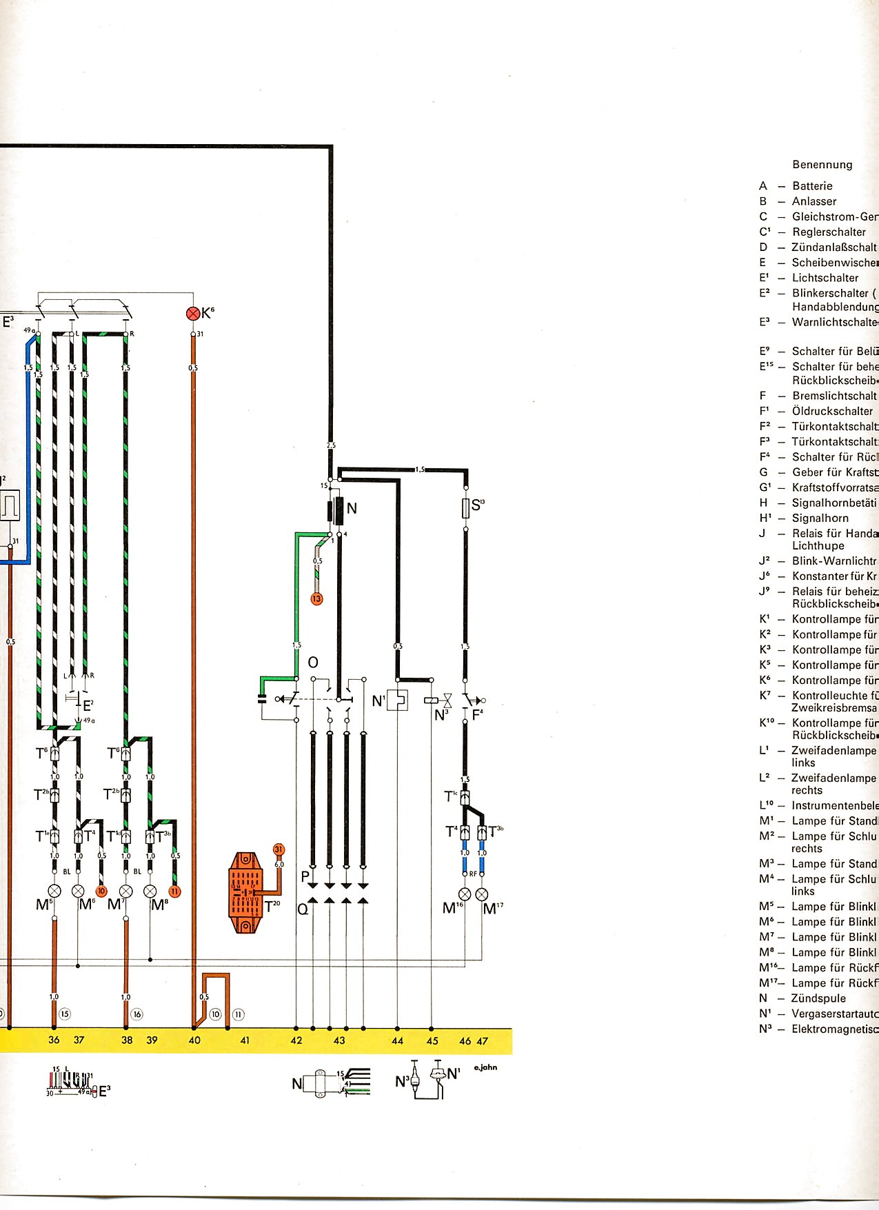 3
3 4
4 5
5 6
6 1
1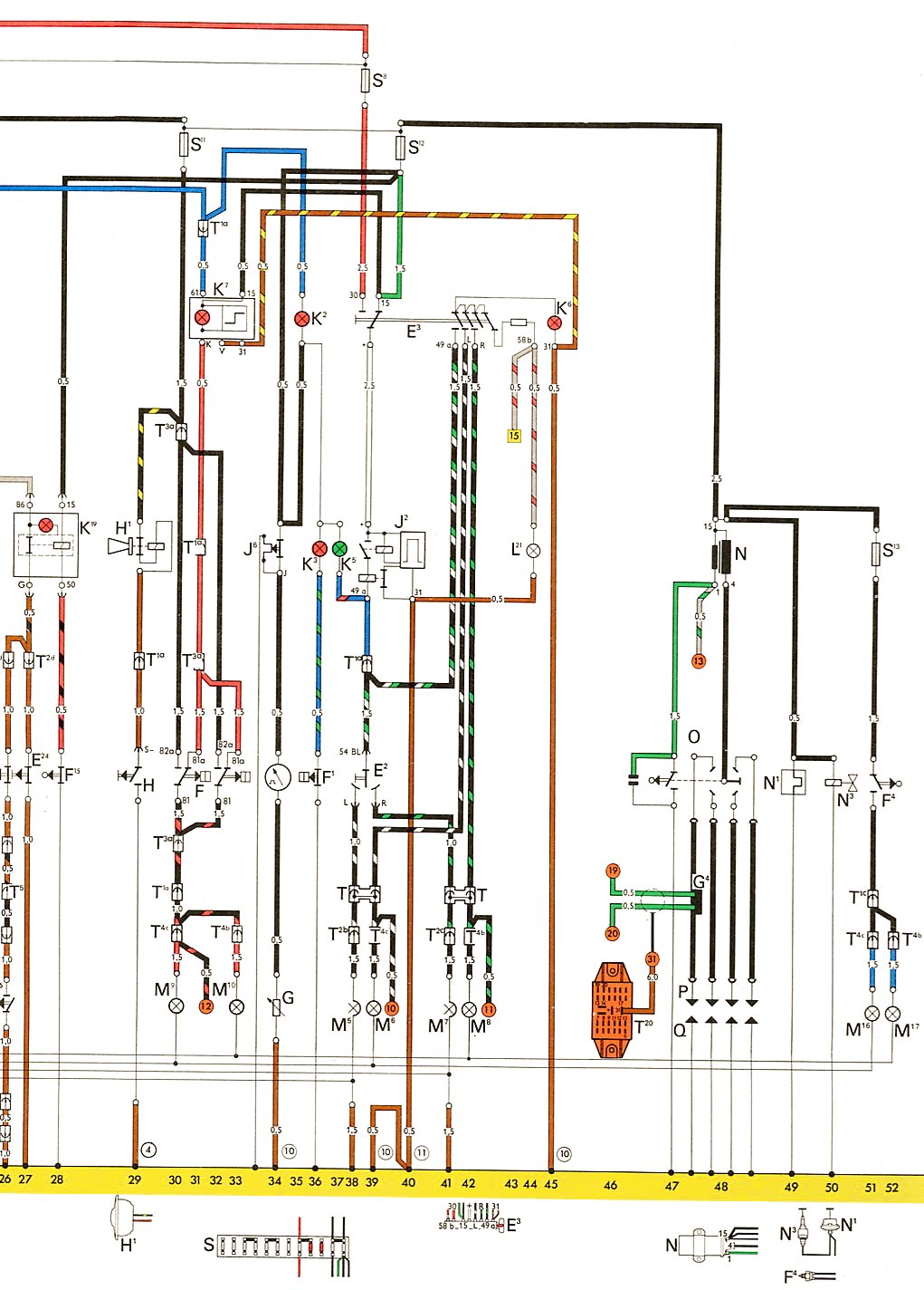 2
2 3
3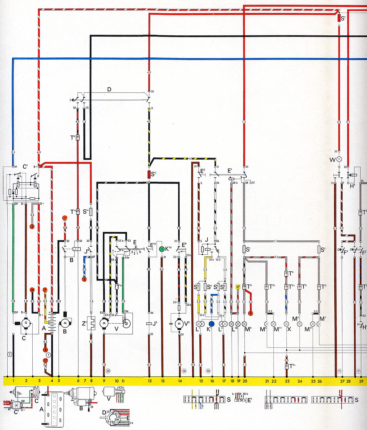 1
1 2
2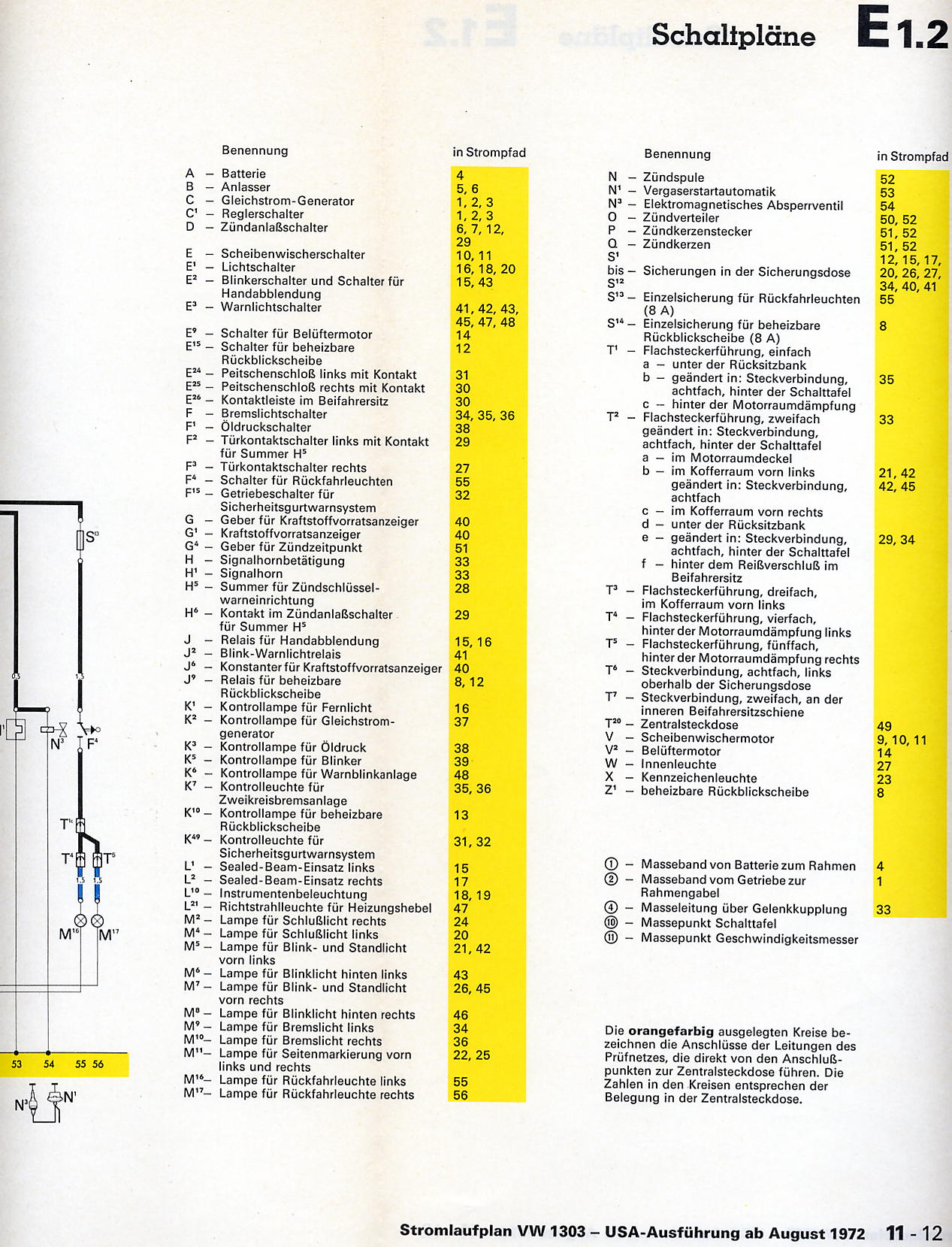 3
3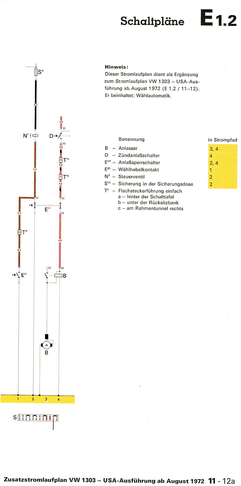 4
4 1
1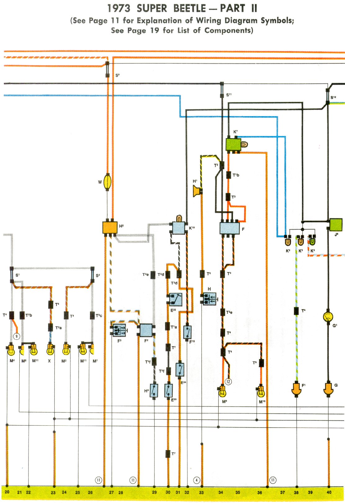 2
2 3
3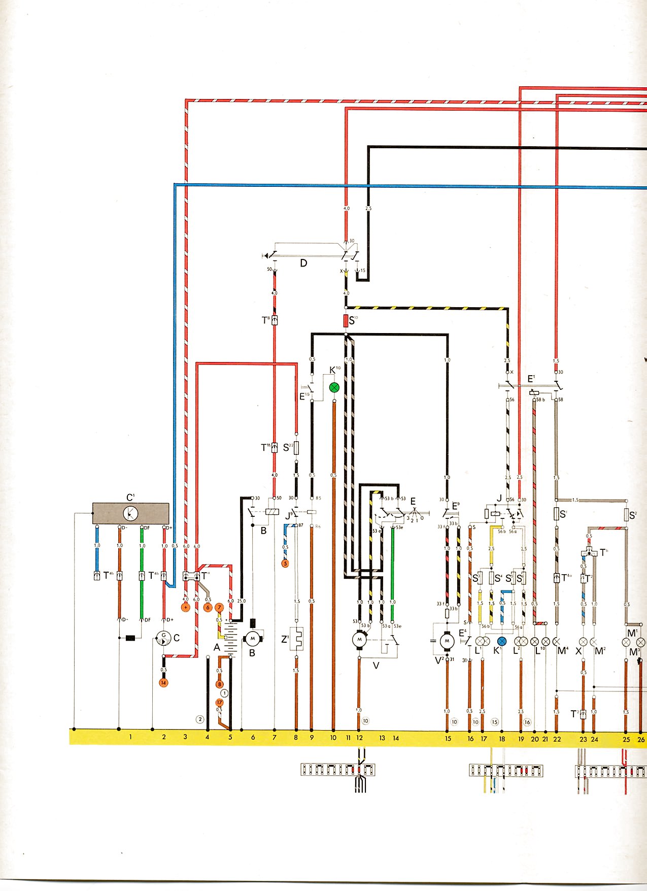 1
1 2
2 3
3 4
4 1
1 2
2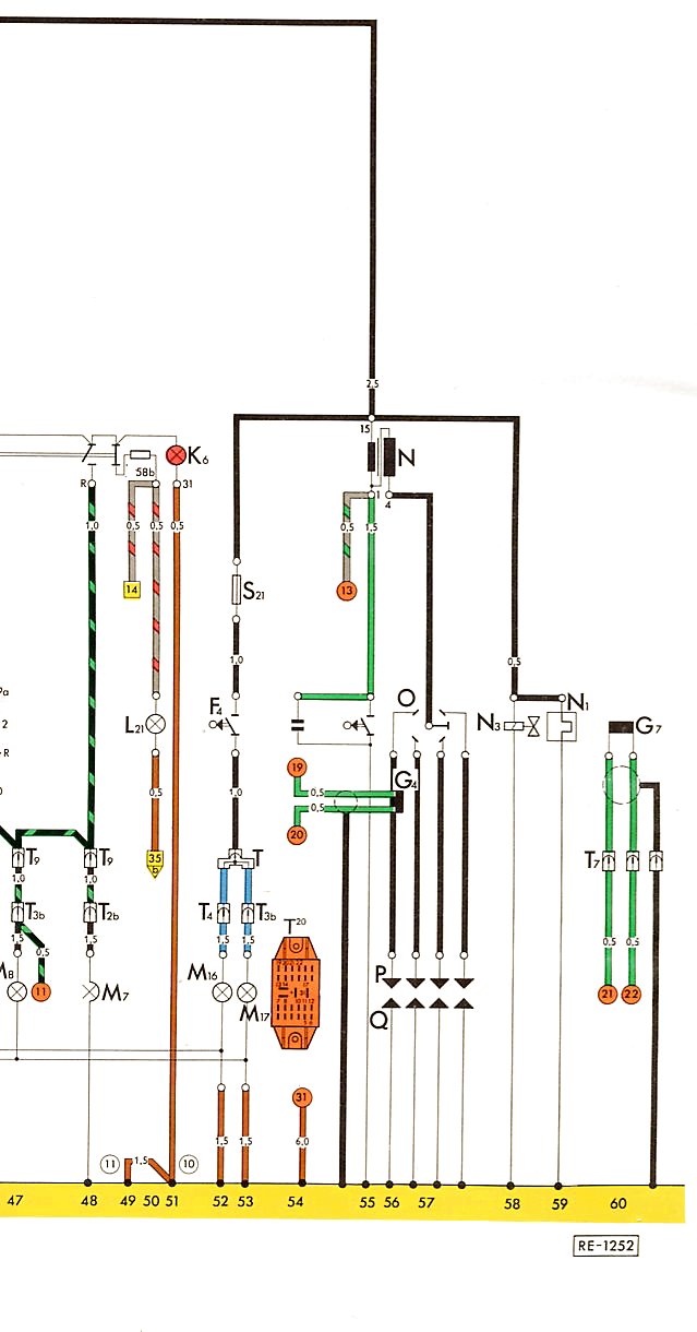 3
3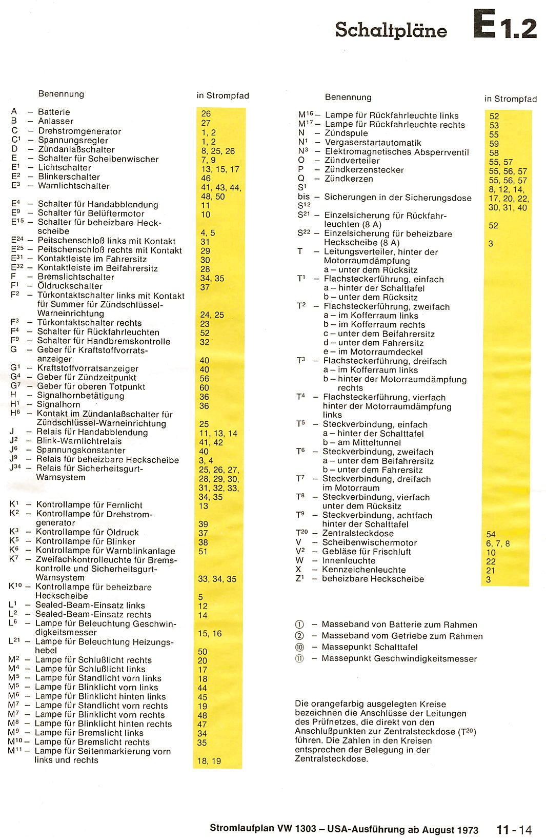 4
4 1
1 2
2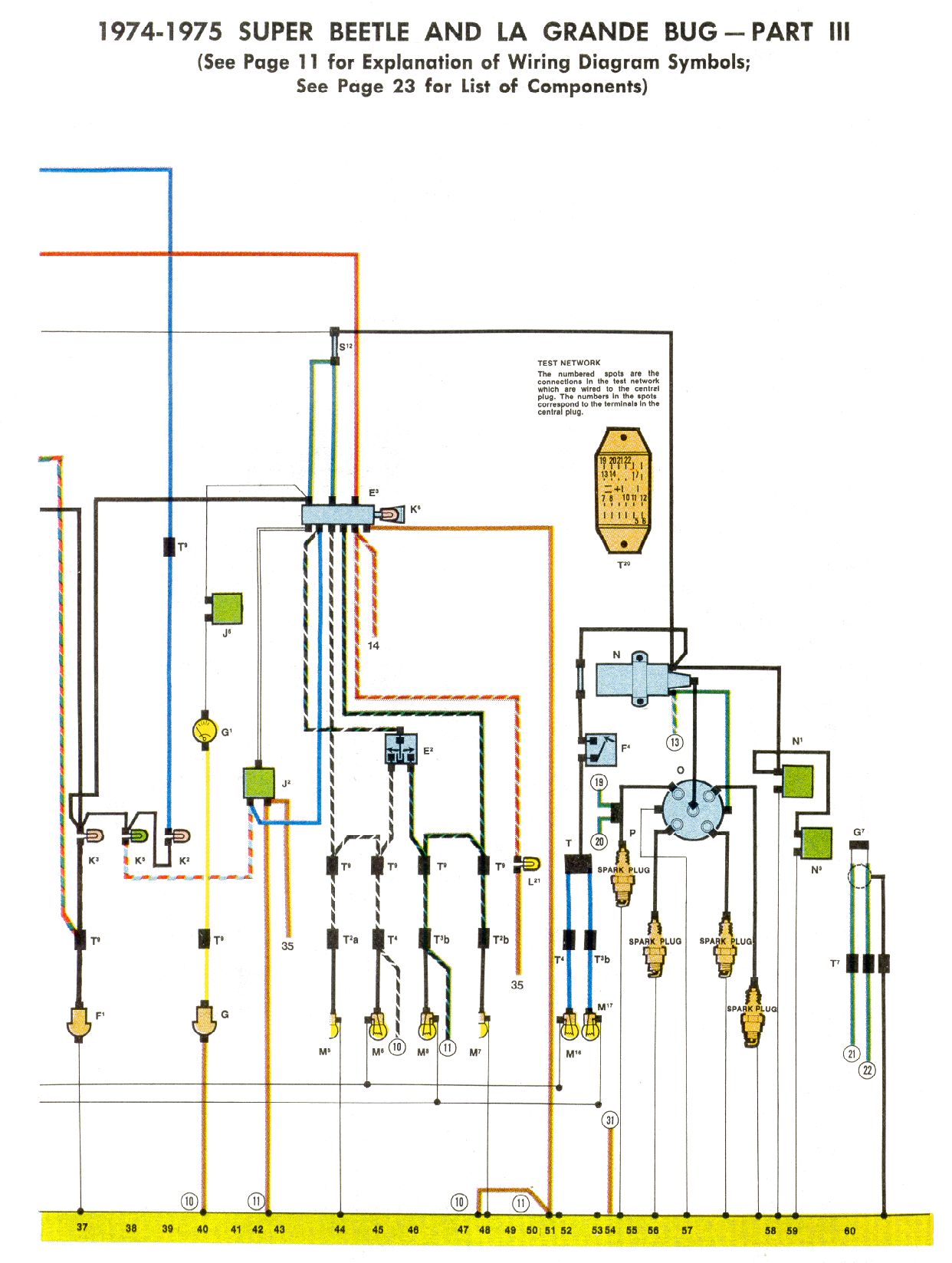 3
3Karmann Ghia
| Year | Comment |
Key
|
Fuse Block
|
Diagram
|
|---|---|---|---|---|
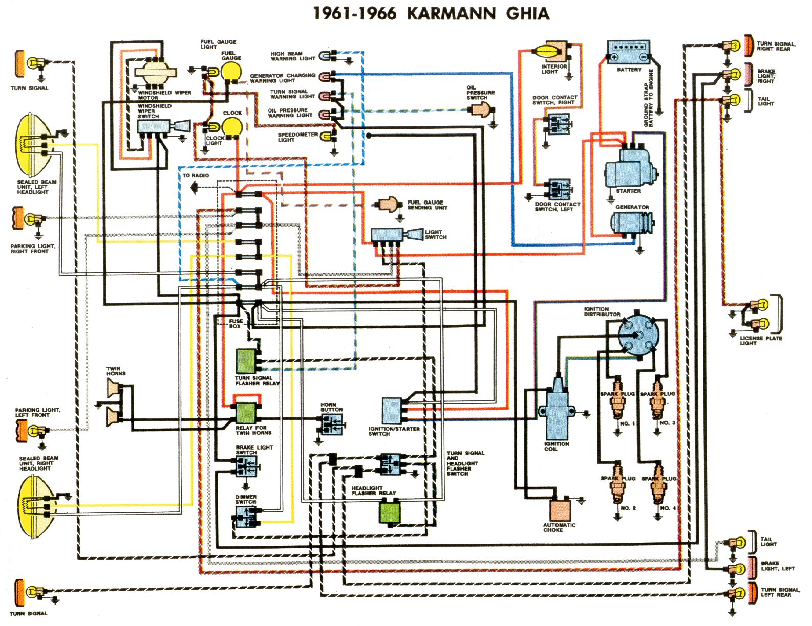
| 1961-1966 | Clymer |
|
|
 |
| 1961-1963 | Type 3 Ghia |
 |
 |
 |
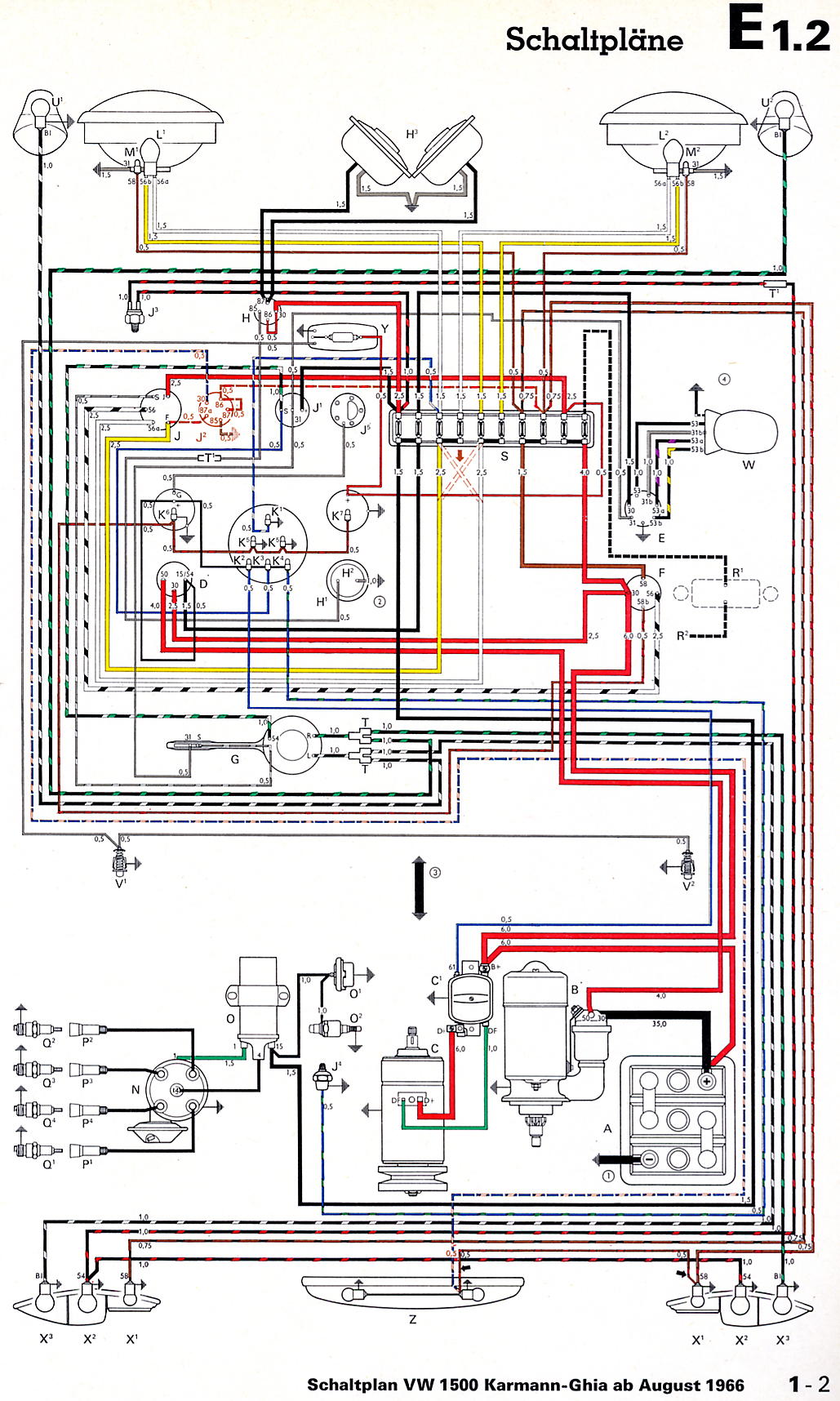
| 1964 | Type 3 Ghia |
 |
|
 |
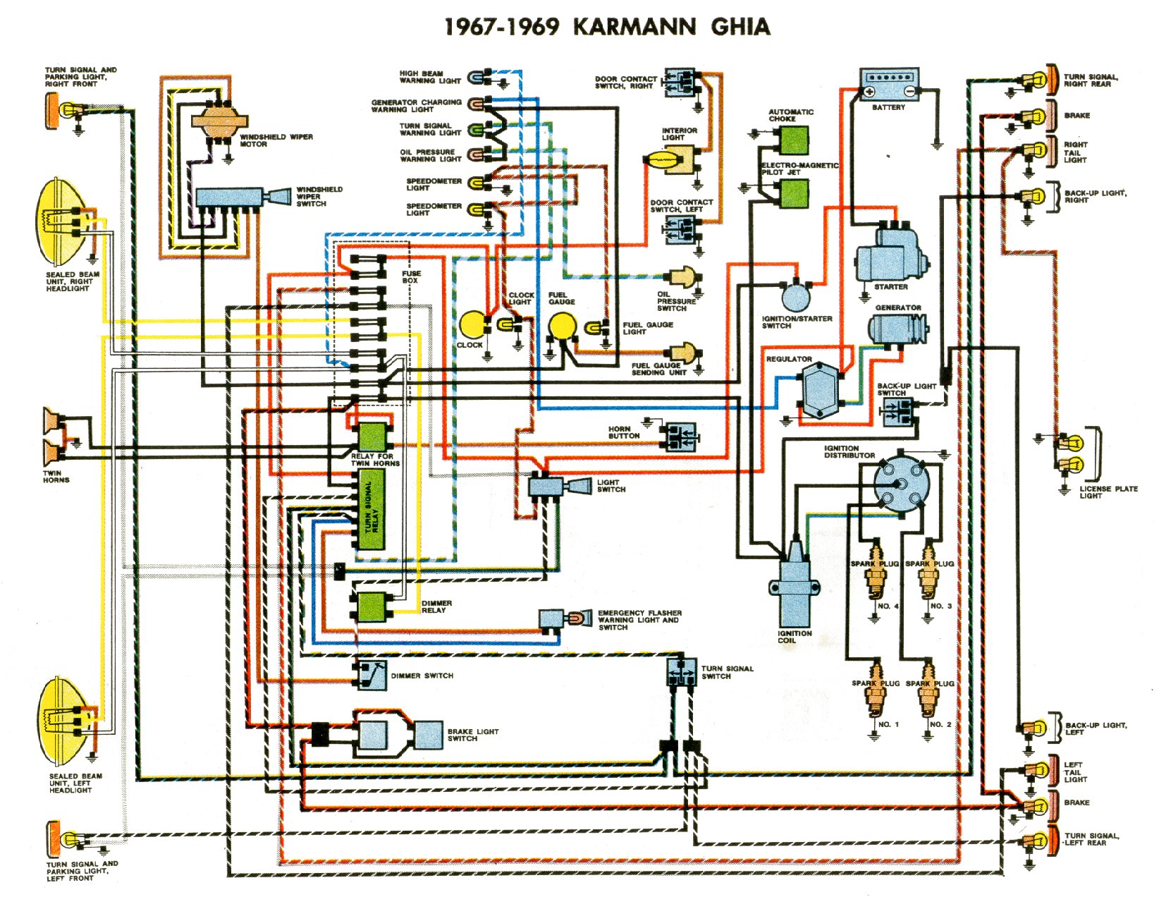
| 1967-1969 |
|
|
 |
|
| 1967 |
|
|
 |
|
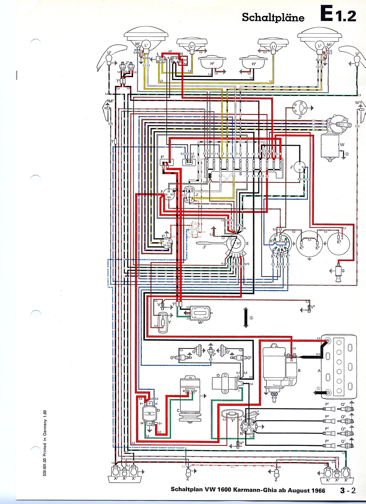
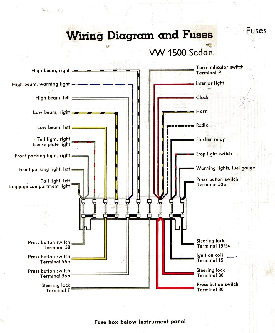
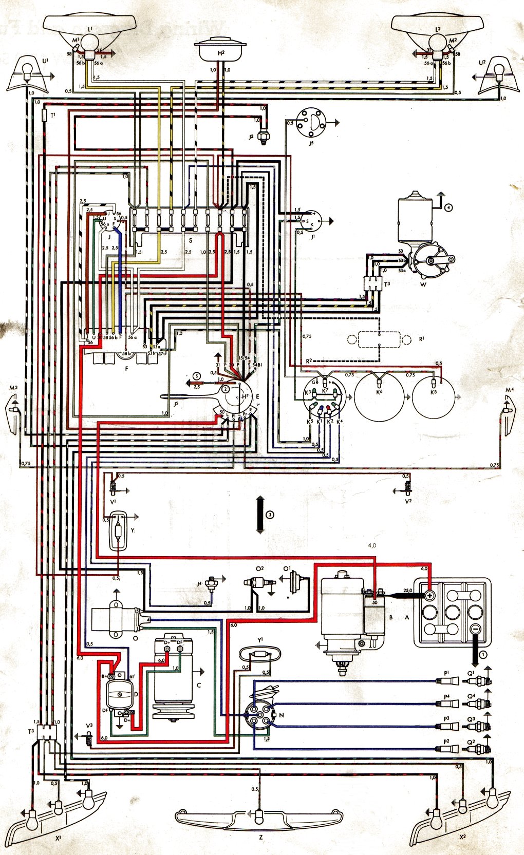
| 1967 | 1500 |
|
|
 |
| 1967 | 1500 USA |
|
|
 |
| 1967 | 1600 |
|
|
 |
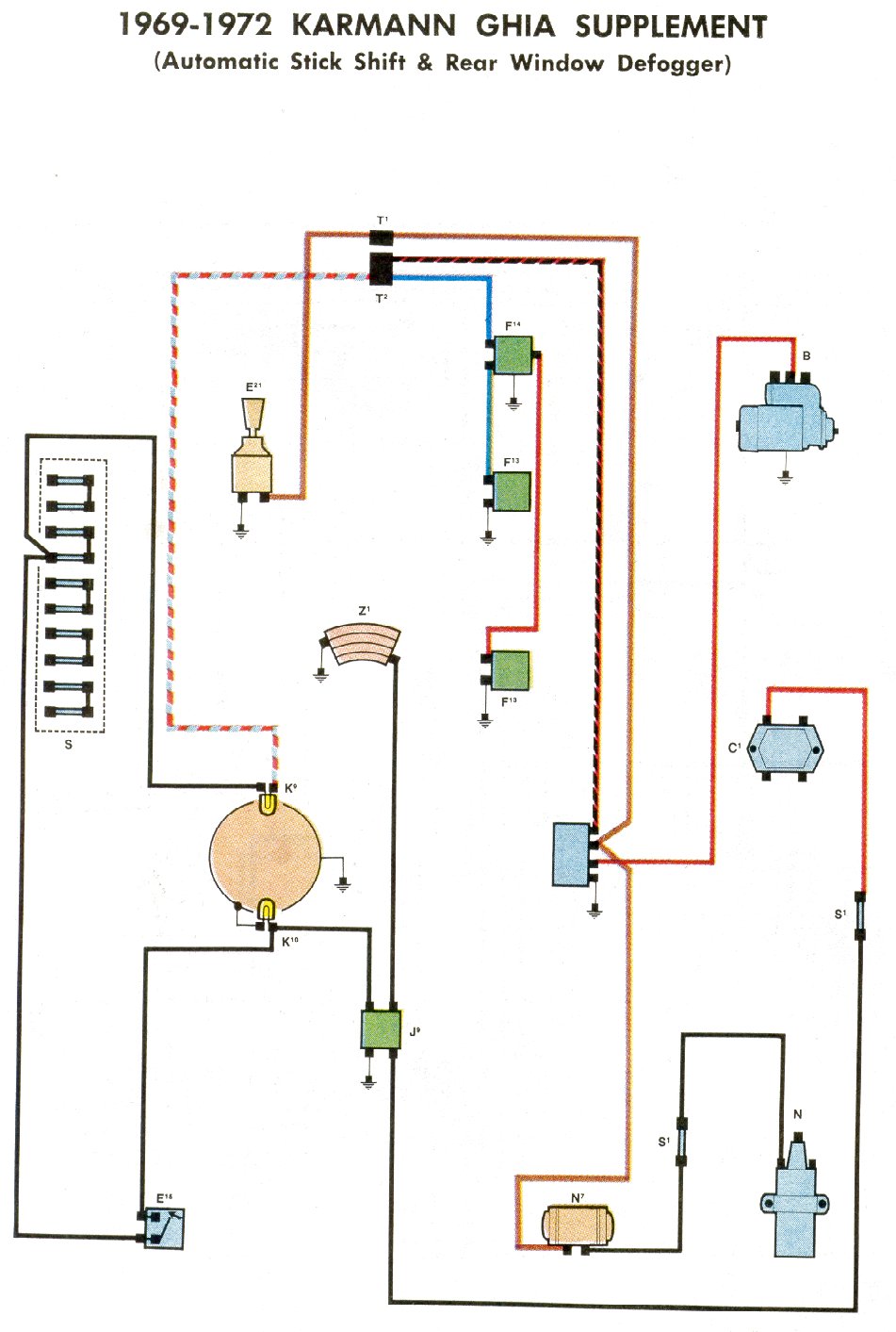
| 1969-1972 | Supplement |
|
|
 |
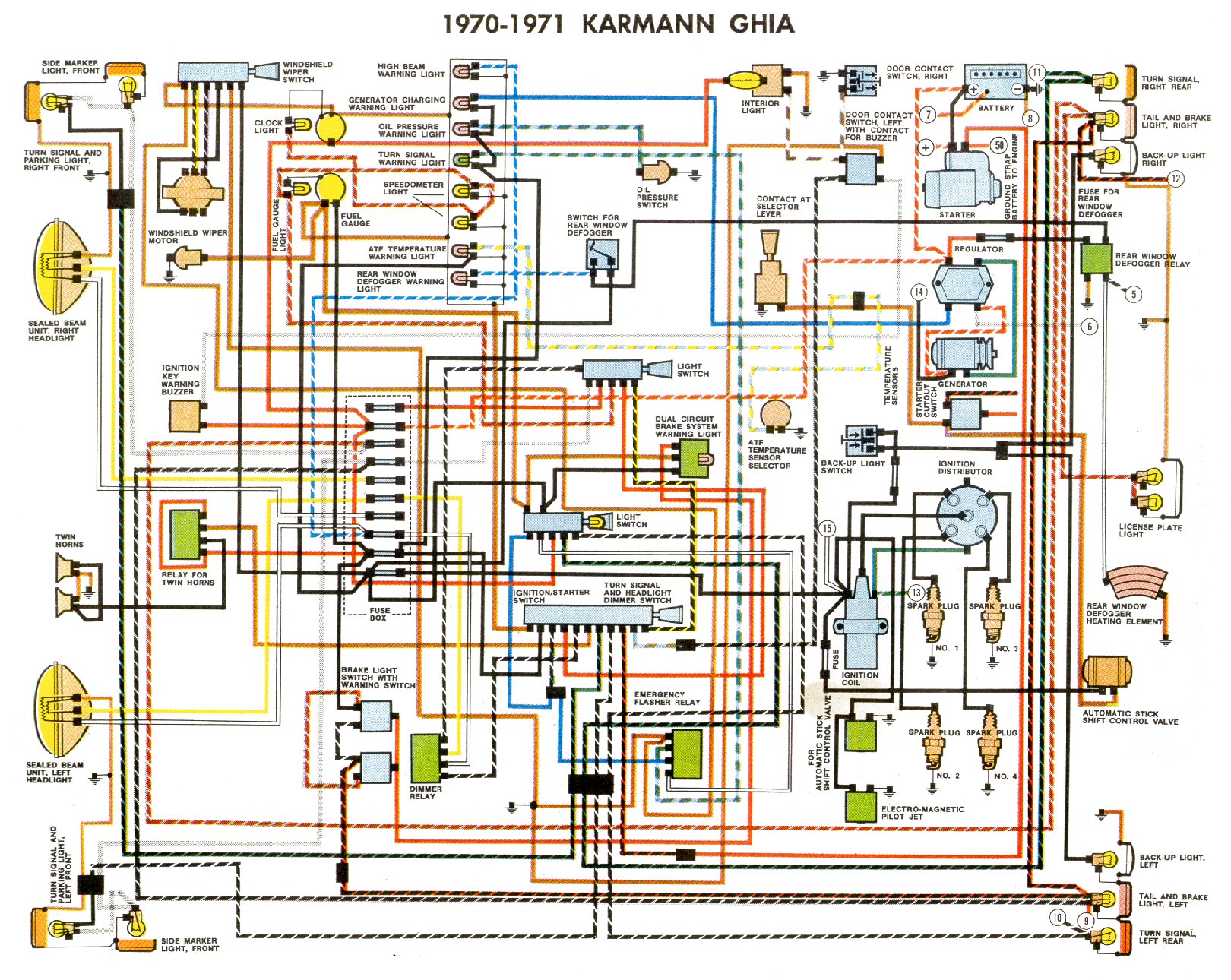
| 1970-1971 |
|
|
 |
|
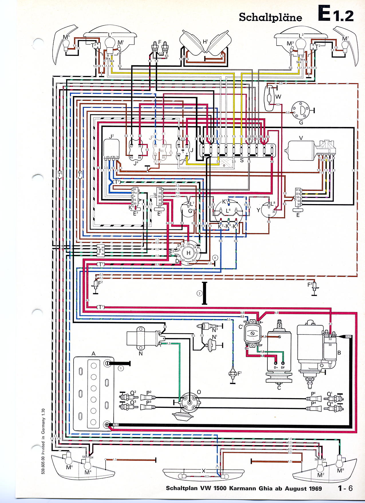
| 1970 | 1500 |
|
|
 |
| 1970 | USA |
|
|
|
| 1971 | Non-USA |
|
|
|
| 1971 | USA |
|
|
|
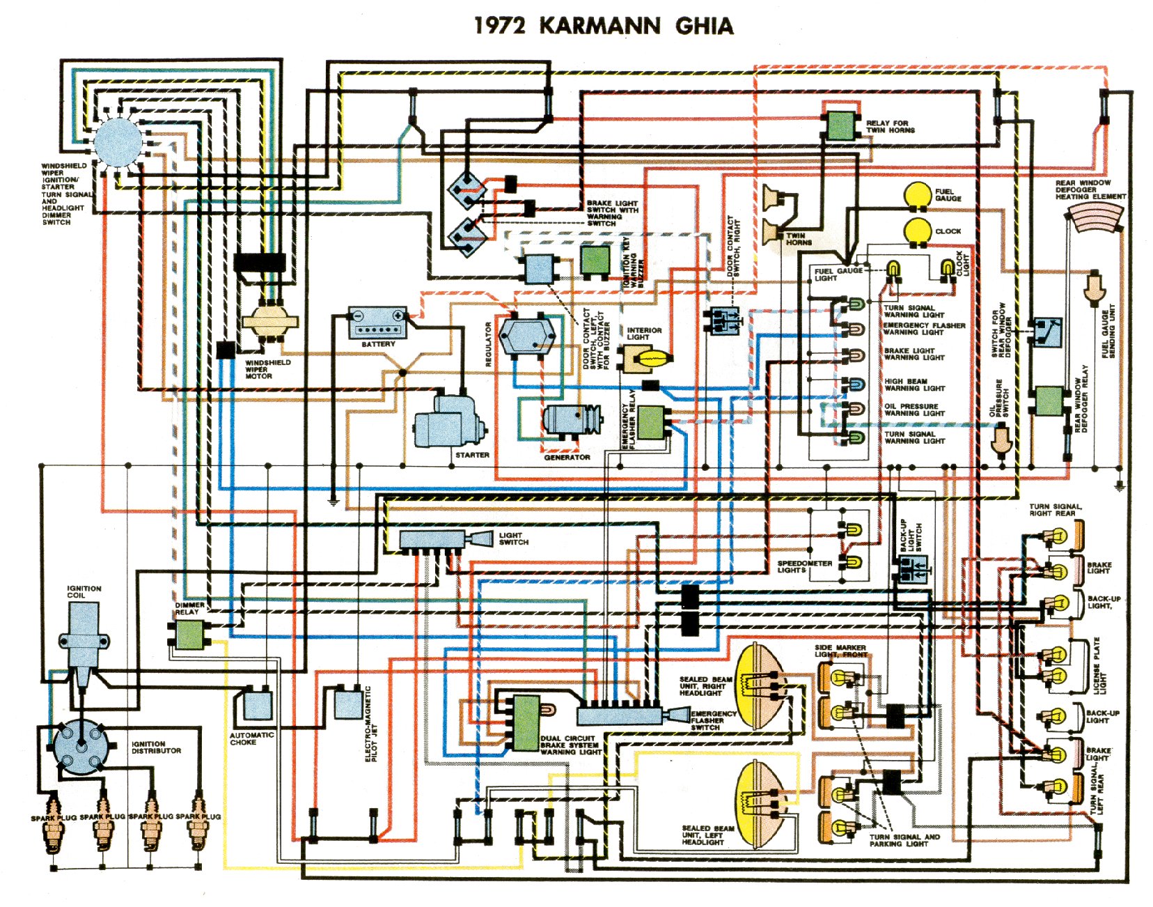
| 1972 | USA |
|
|
|
| 1972 |
|
|
 |
|
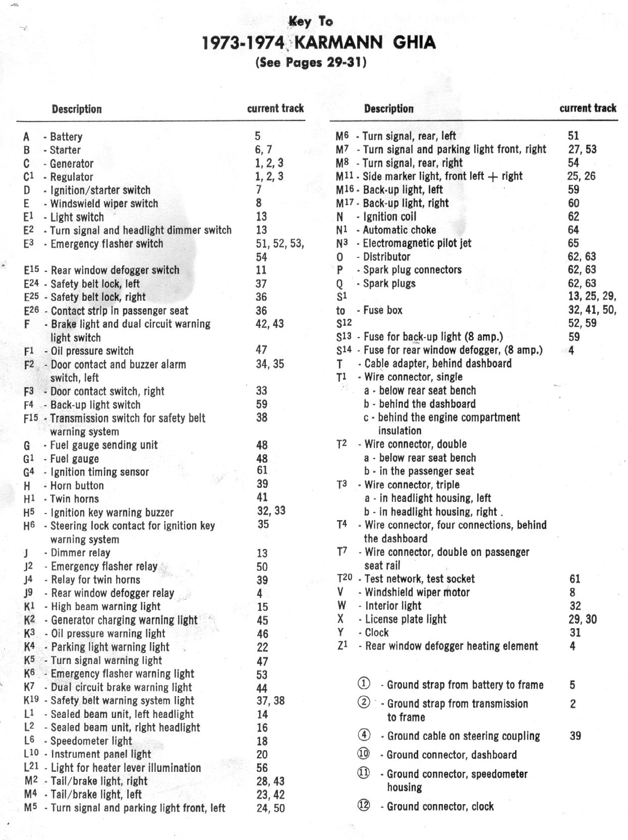
| 1973-1974 |
 |
|
||
| 1973 | Non-USA |
|
|
|
| 1973 | USA |
|
|
 1
1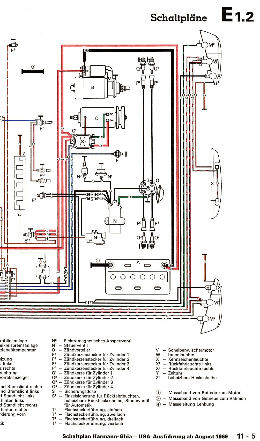 2
2 1
1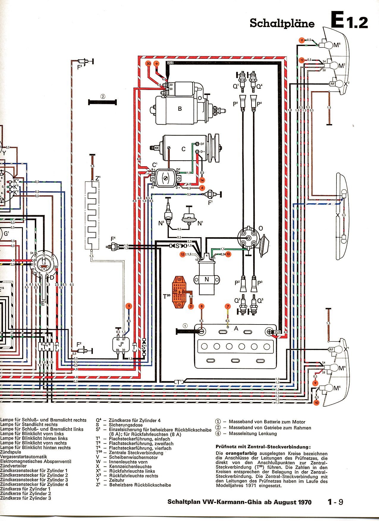 2
2 1
1 2
2 1
1 2
2 1
1 2
2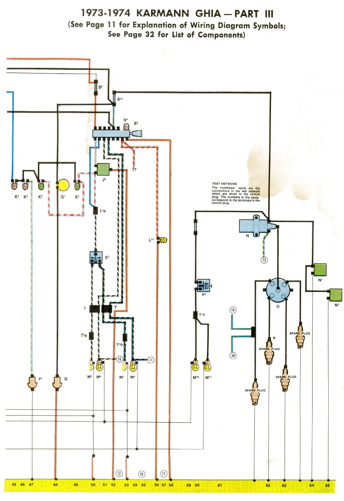 3
3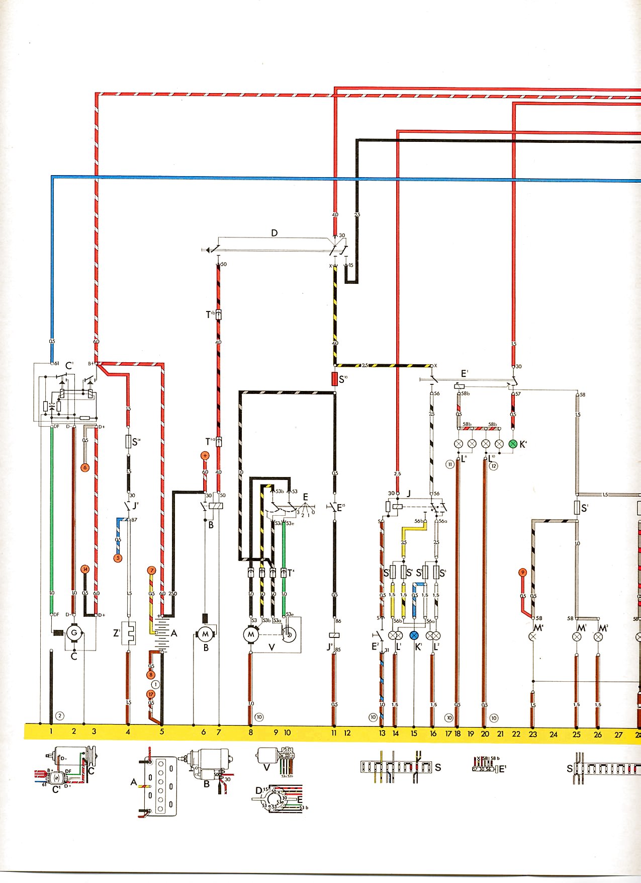 1
1 2
2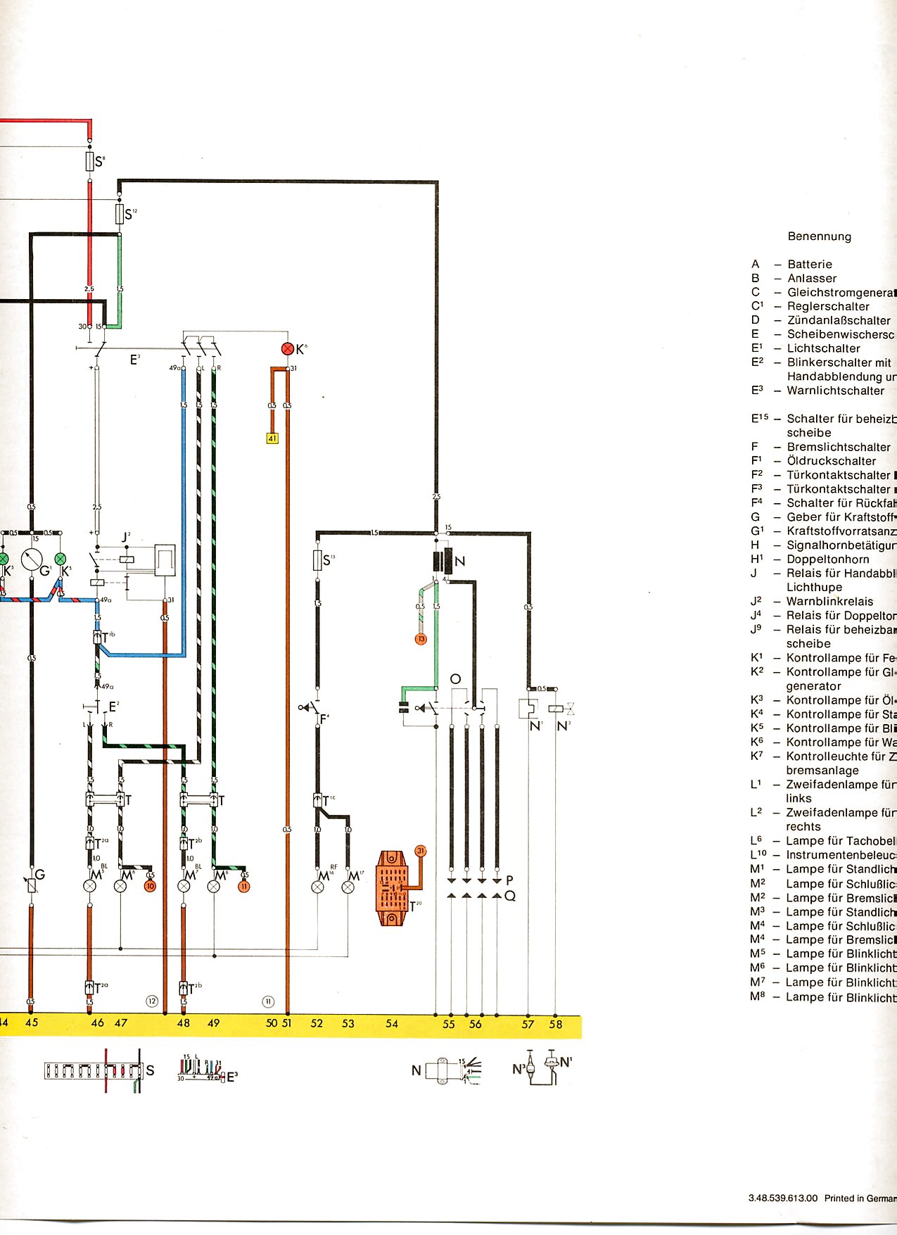 3
3 4
4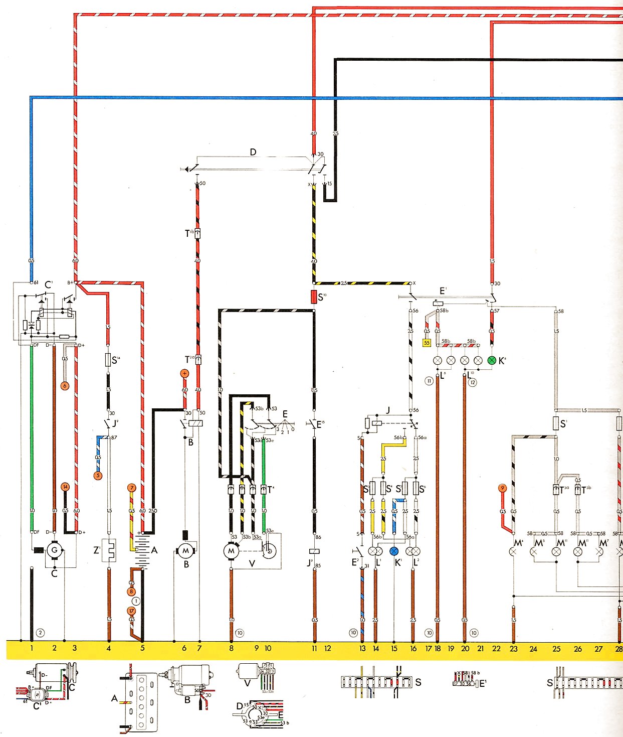 1
1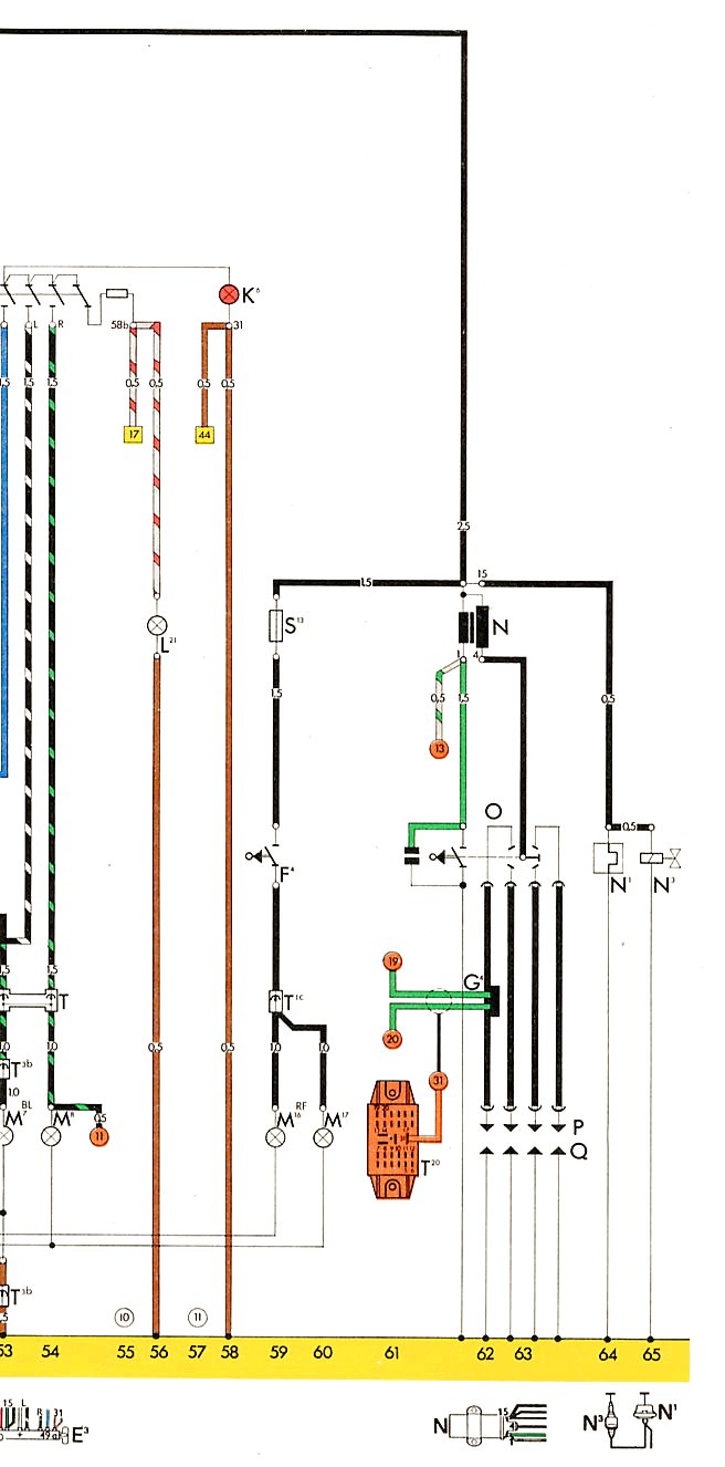 2
2 3
3Type 3
| Year | Comment |
Key
|
Fuse Block
|
Diagram
|
|---|---|---|---|---|
| 1961-1963 | 1500 |
 |
 |
 |
| 1961-1963 | Ghia |
|
|
|
| 1964 | Ghia |
|
|
|
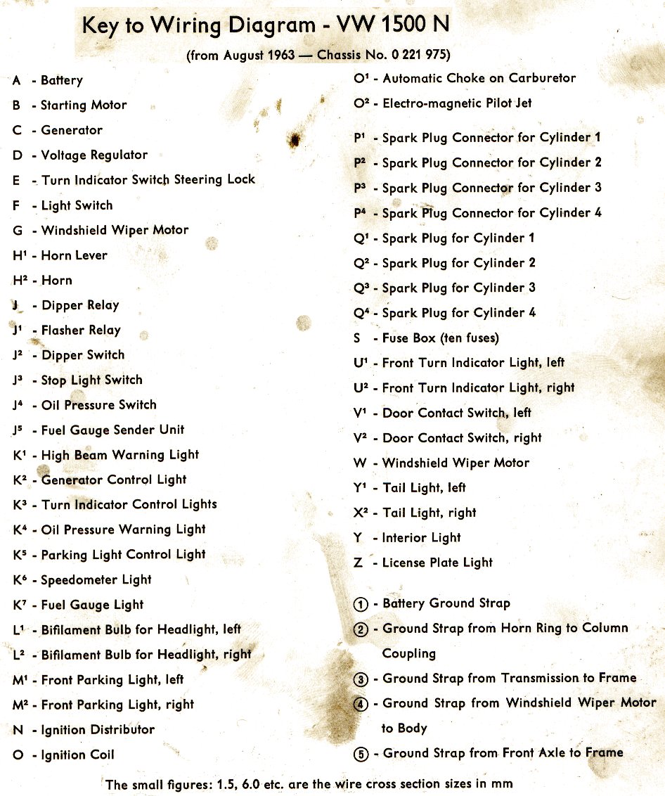
| 1964-1965 | 1500 N |
 |
 |
 |
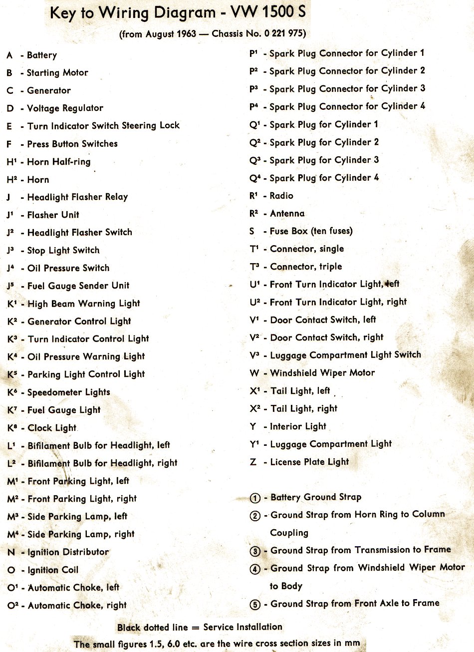
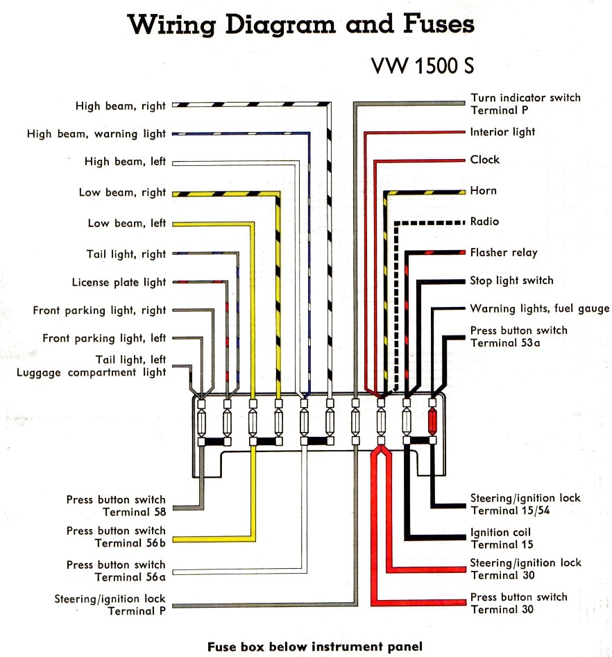
| 1964-1965 | 1500 S |
 |
 |
 |
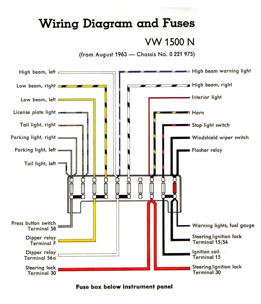
| 1964 | 0 221 975 - Non-USA |
|
|
 |
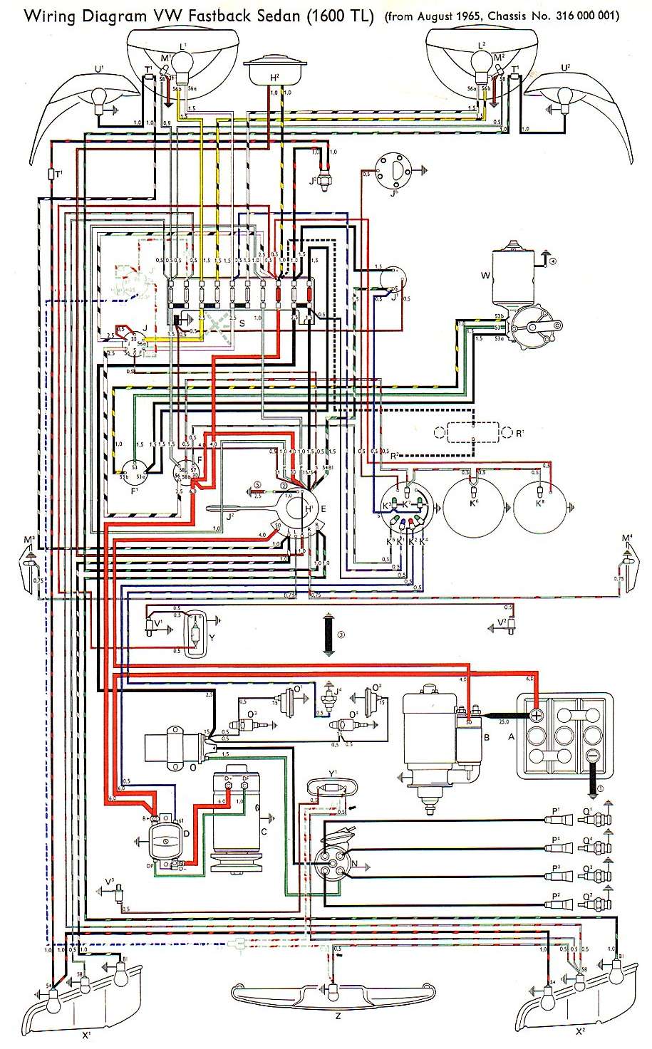
| 1966 | 316 000 001 |
|
|
 |
| 1967 | 1600 |
|
|
 |
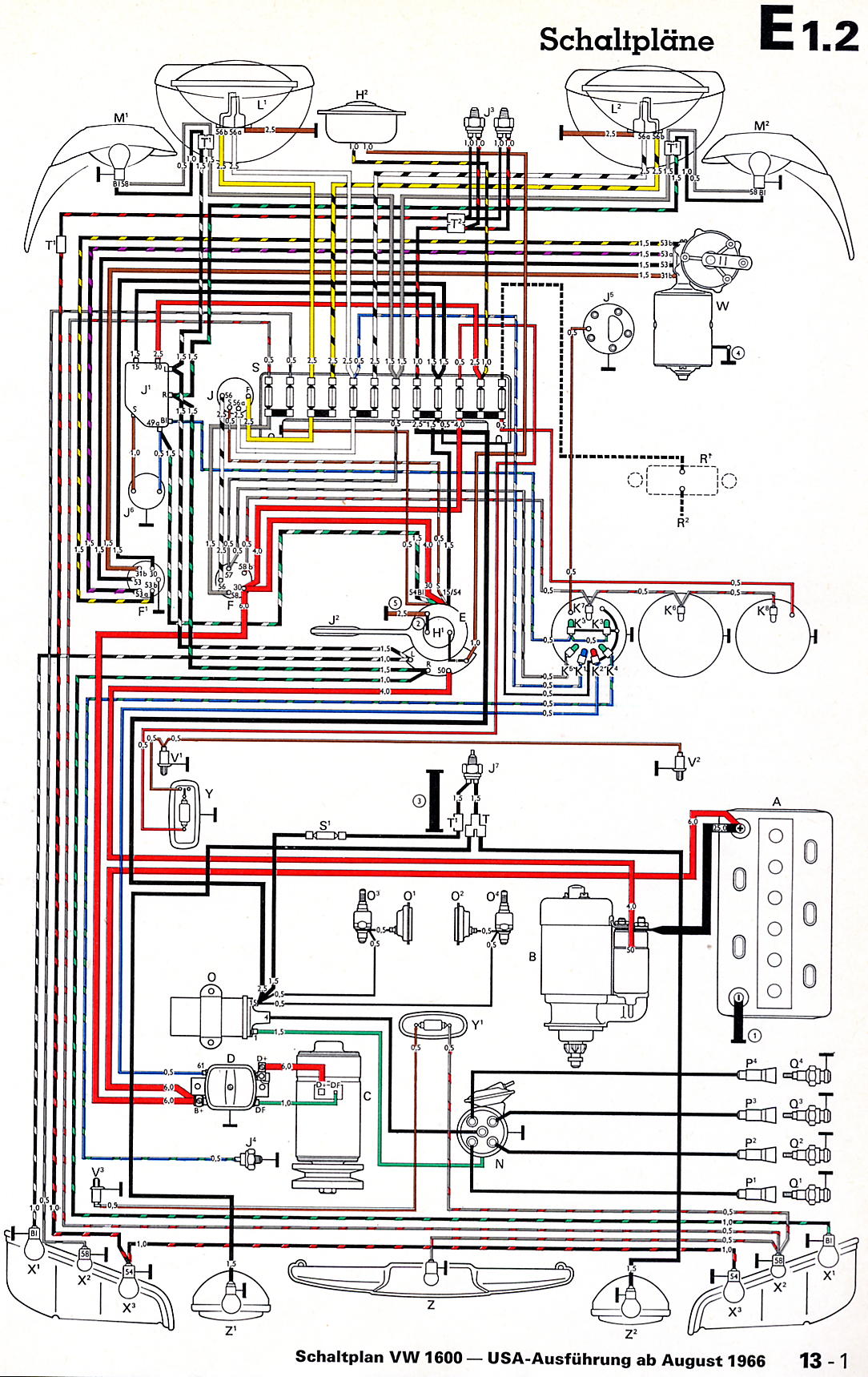
| 1967 | 1600 USA |
|
|
 |
| 1968 | 1500 |
|
|
 |
| 1968 | 1500 USA |
|
|
 |
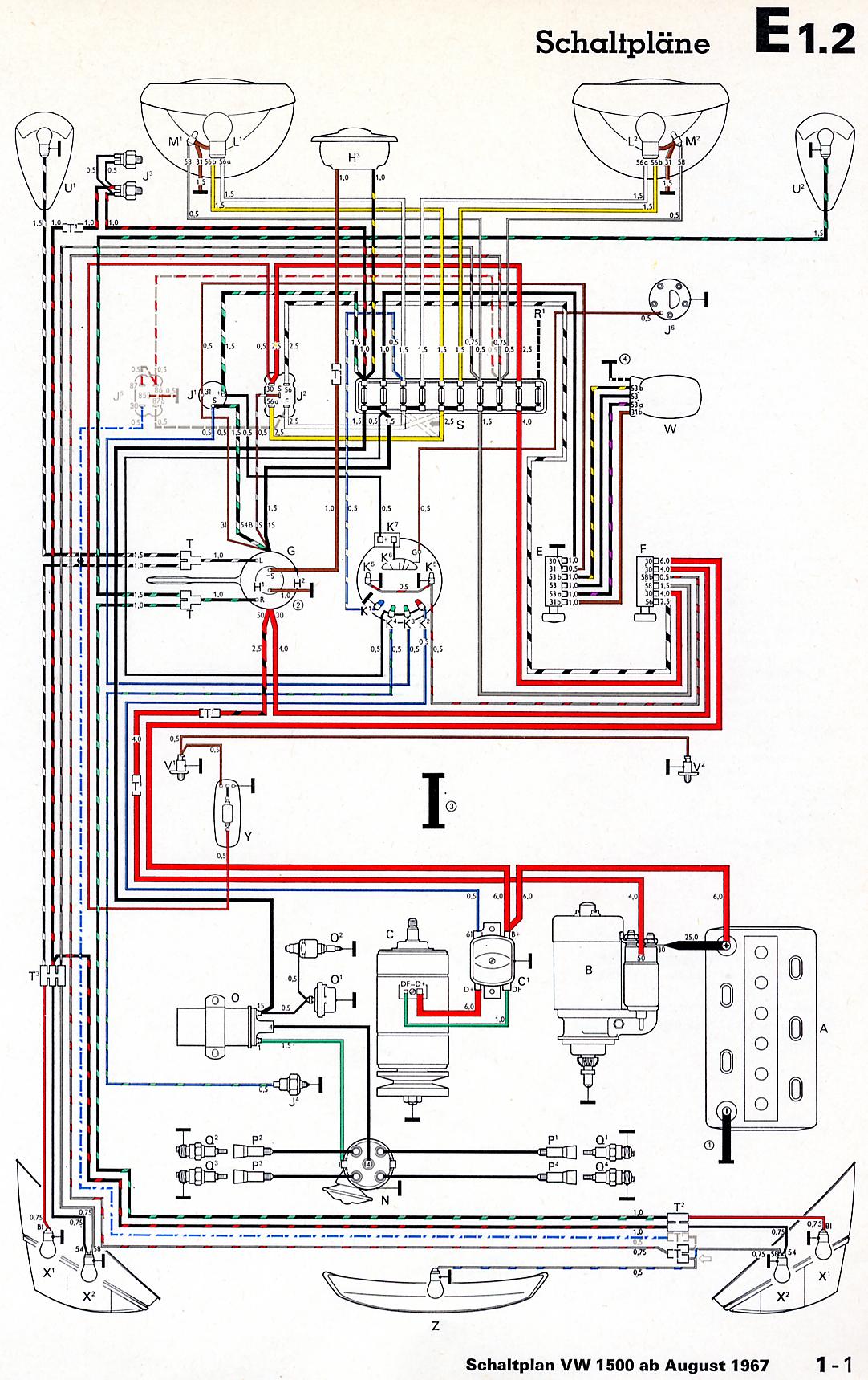
| 1969 | 1500 |
|
|
 |
| 1969 | 1600 |
|
|
 |
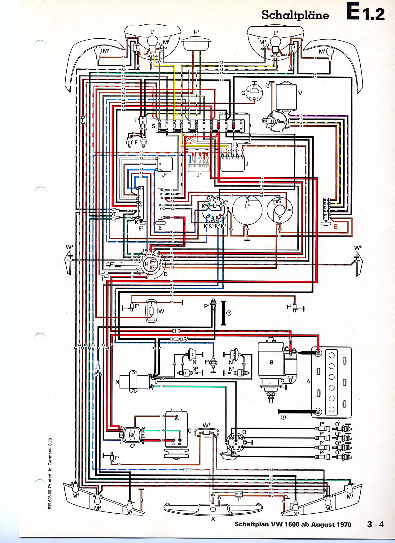
| 1970 | 1600 USA Additional items |
|
|
 |
| 1971 | 1600 with test central socket |
|
|
 |
| 1971 | 1600 without test central socket |
|
|
 |
| 1971 | 311 2000 001 to 311 2500 000 |
|
|
 |
| 1971 | 1600 Additional items |
|
|
 |
| 1972 | Type 3 |
|
|
|
| 1972 | 1600 USA |
|
|
|
| 1972 | Type 3 USA Additional items |
|
|
 |
| 1973 | Type 3 |
|
|
|
| 1973 | Type 3 USA |
|
|
 1
1 2
2 1
1 2
2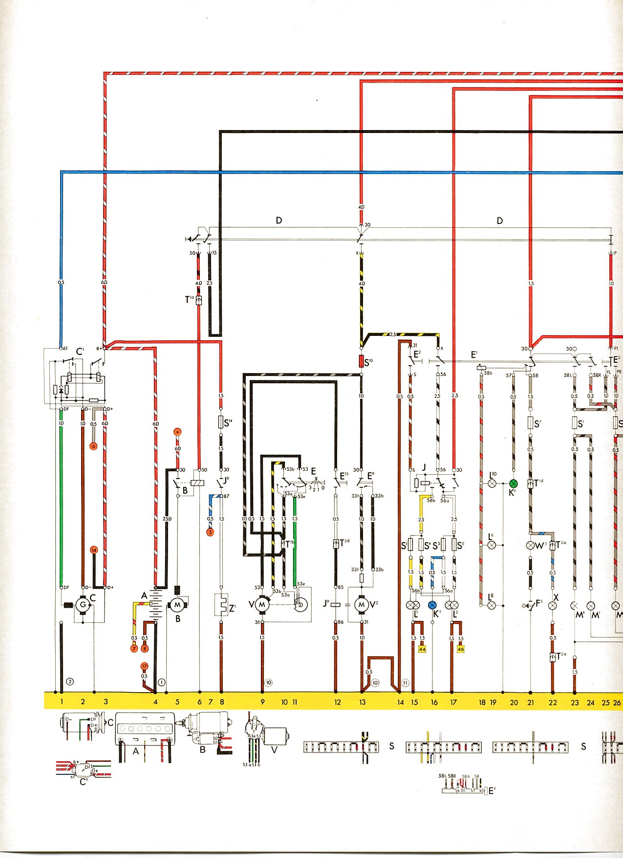 1
1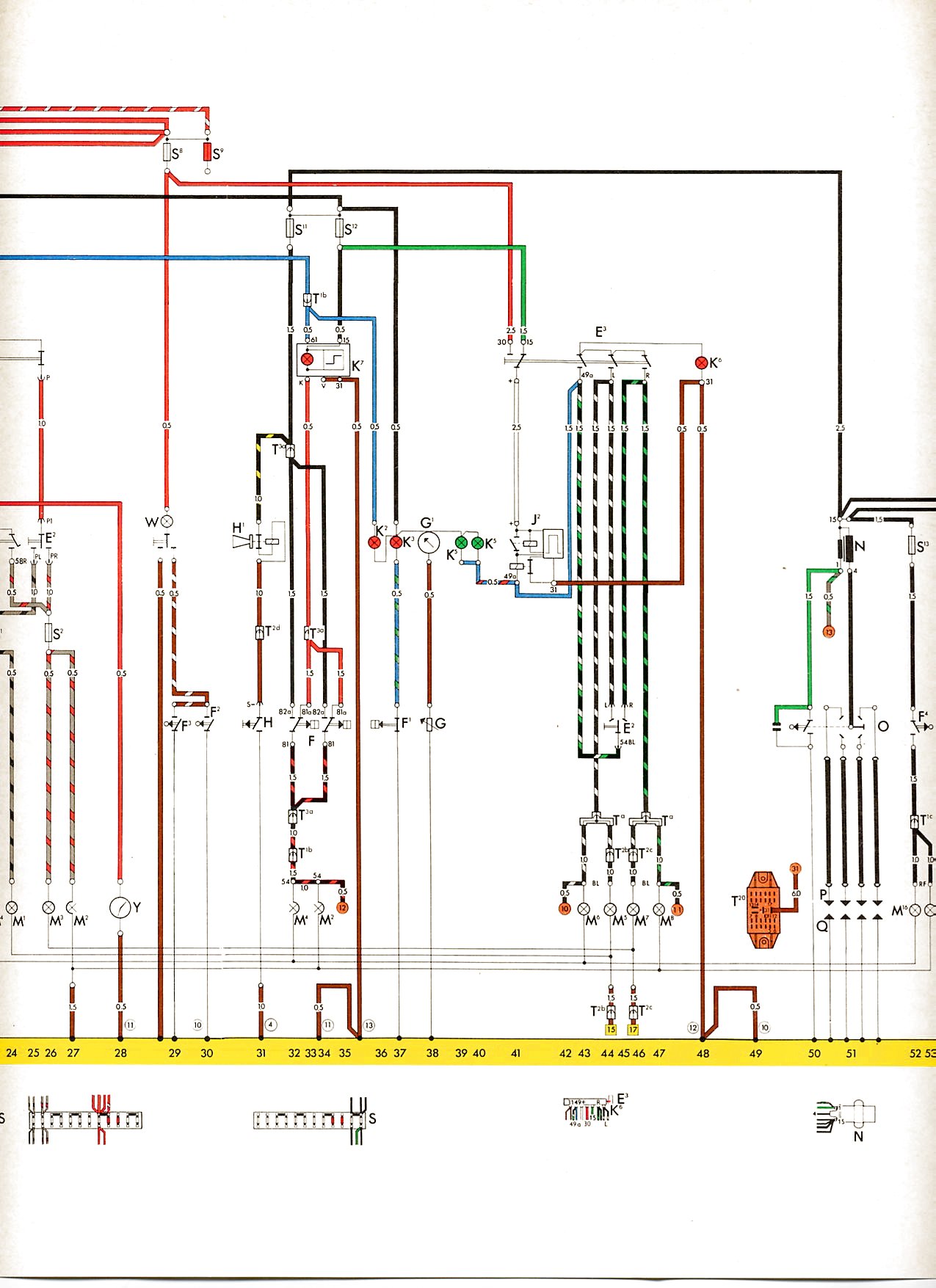 2
2 3
3 4
4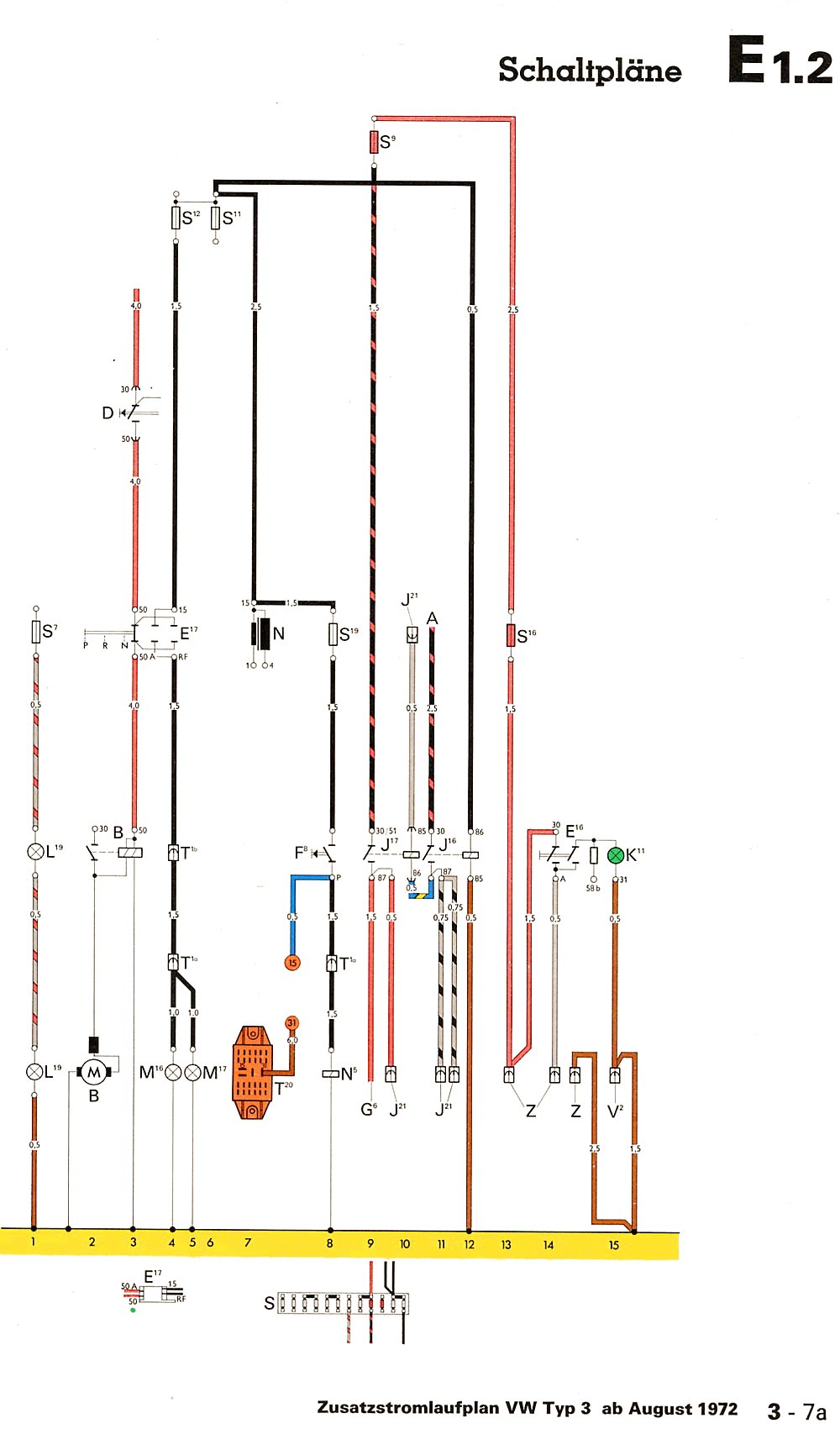 5
5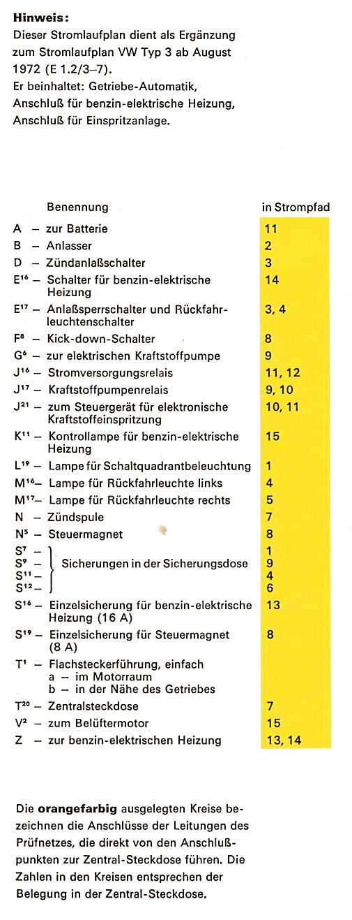 6
6 1
1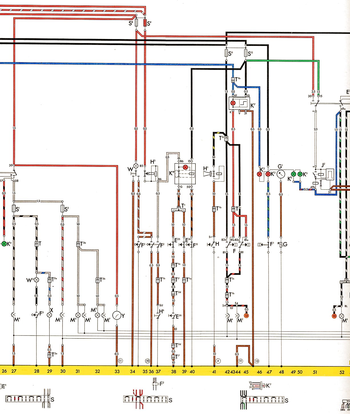 2
2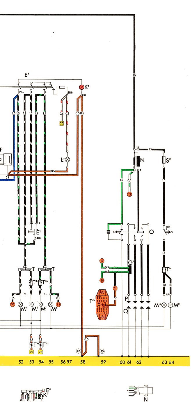 3
3 4
4 5
5Type 4
| Year | Comment | Key | Fuse Block | Diagram |
|---|---|---|---|---|
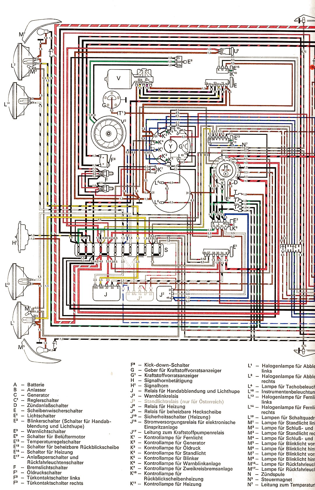
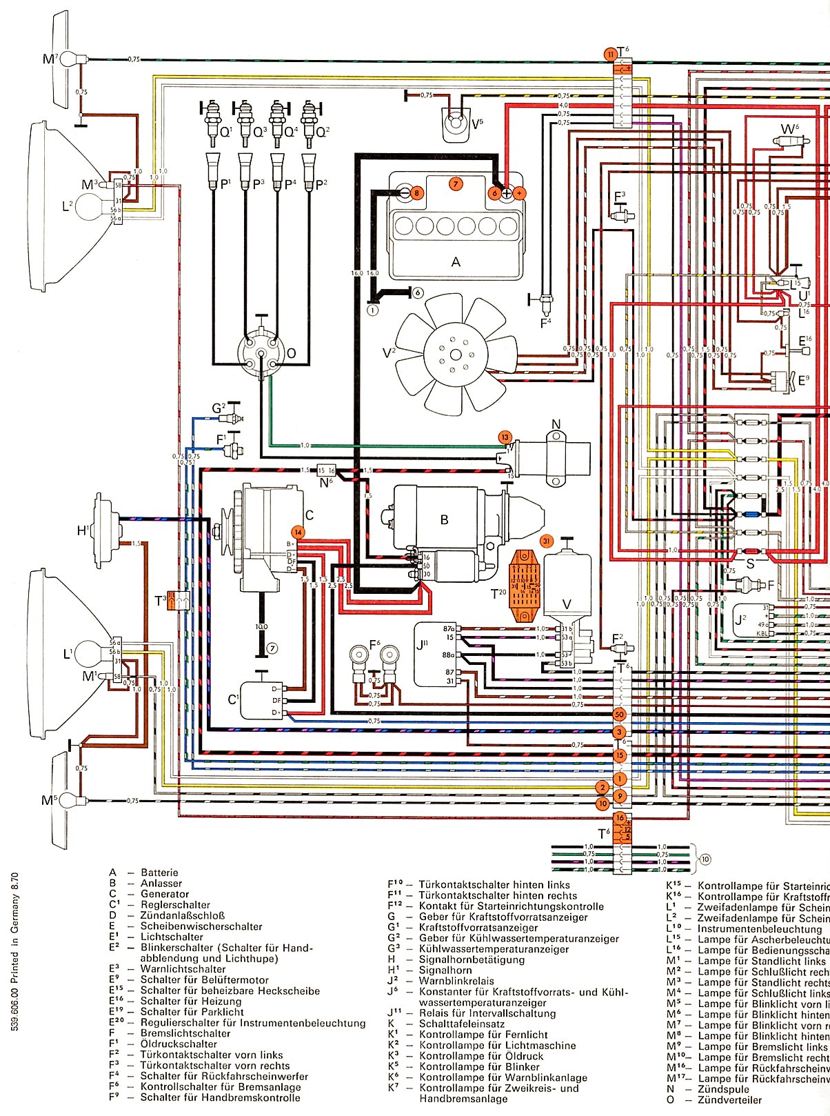
| 1969 | 411 |
 1 1 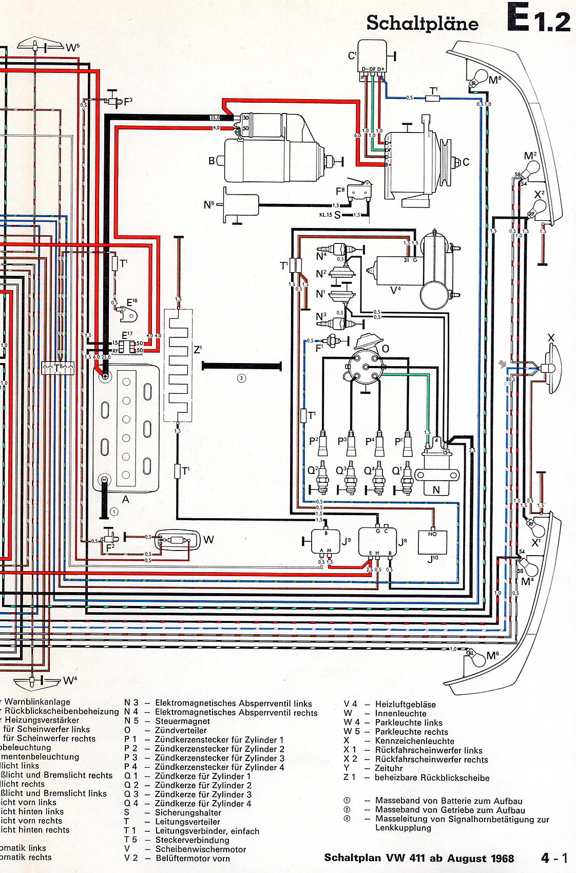 2 2 |
||
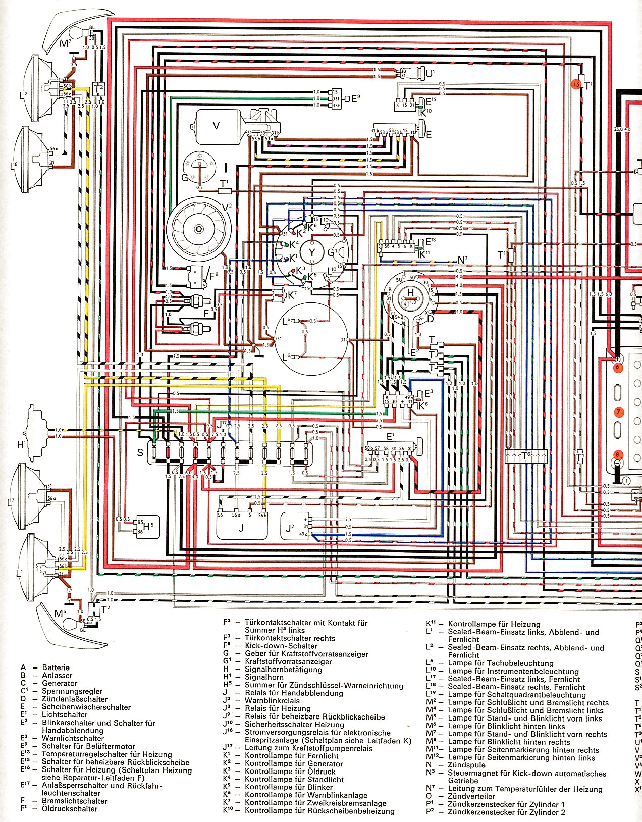
| 1971 | 411 |
 1 1  2 2 |
||
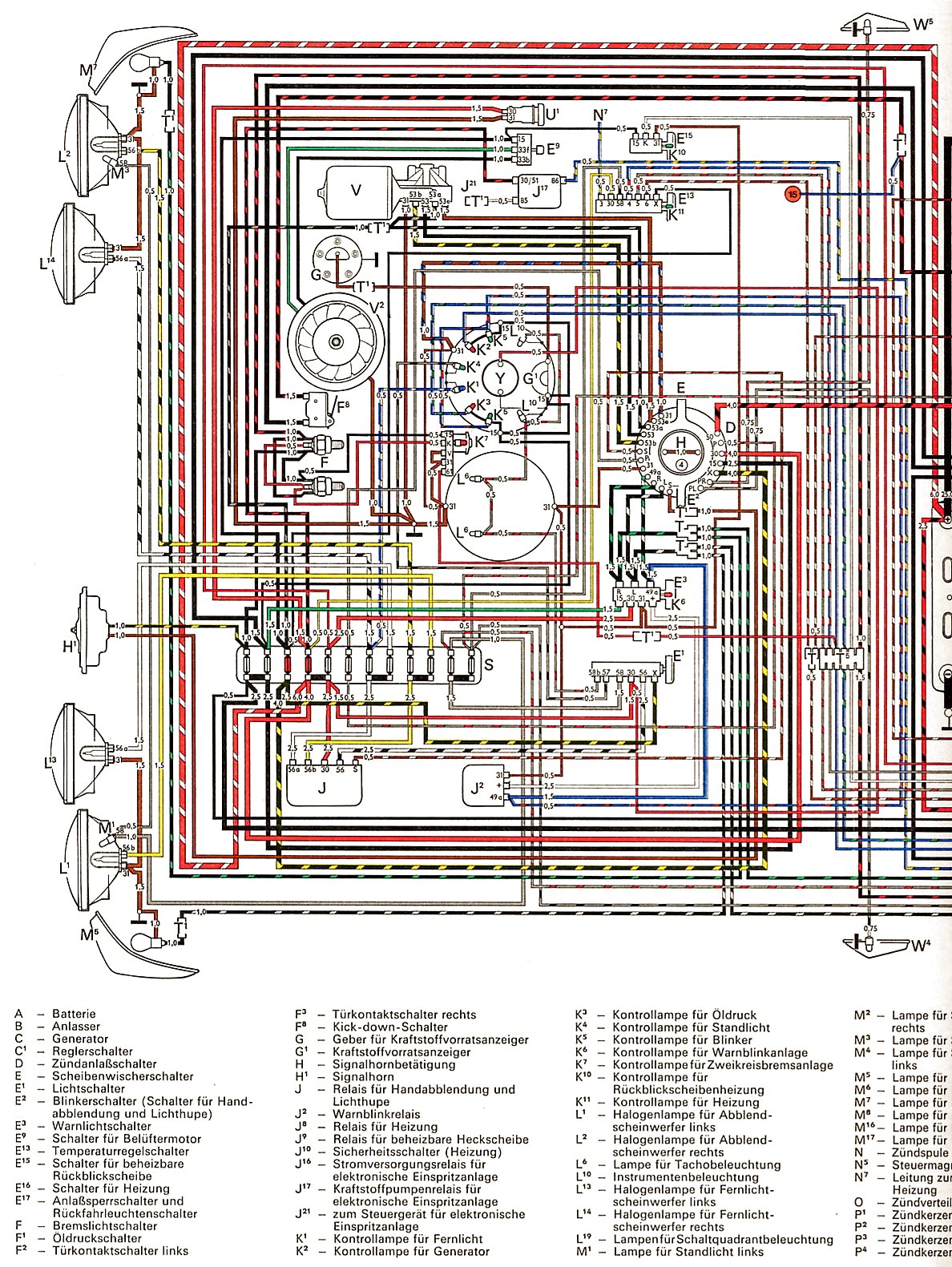
| 1971 | 411 USA without test central socket |
 1 1 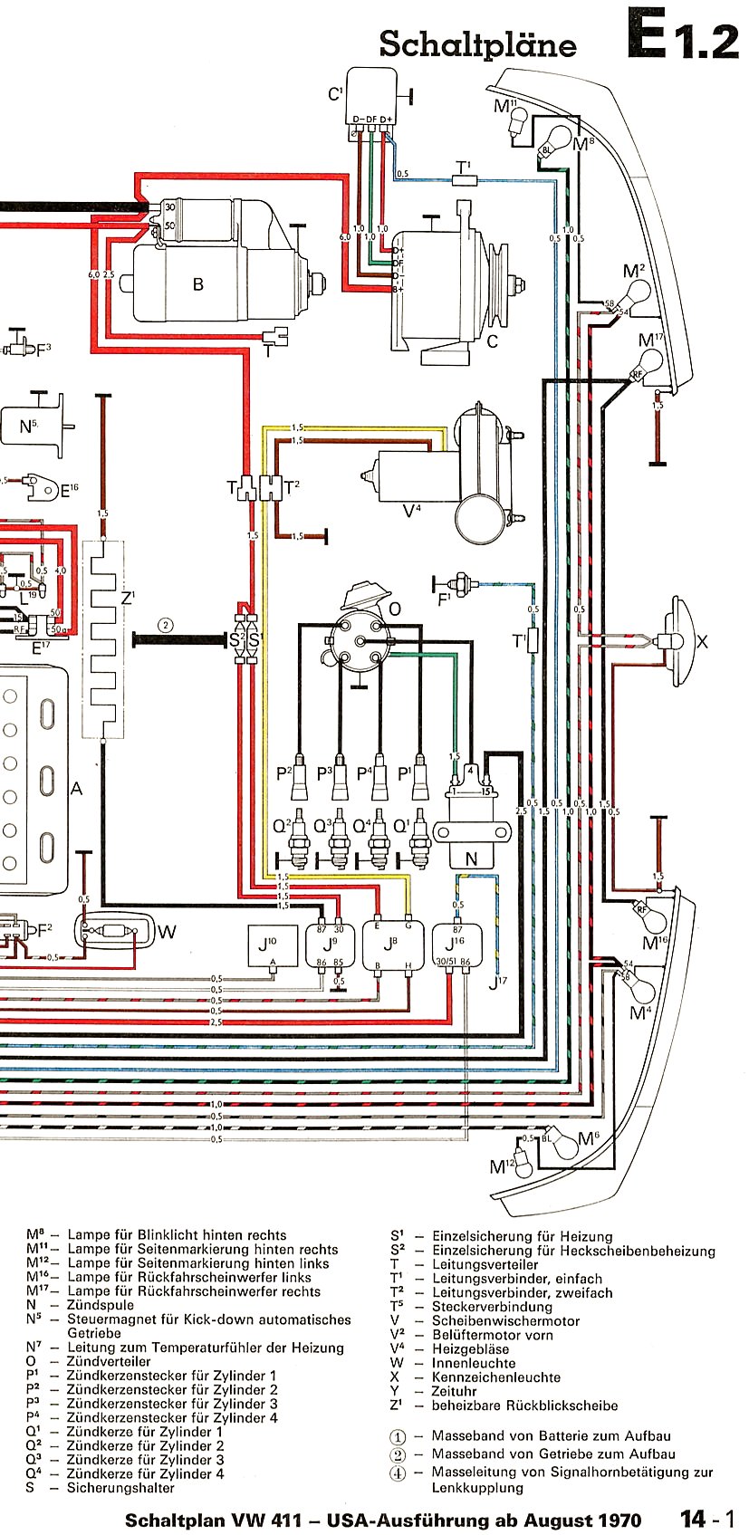 2 2 |
||
| 1971 | 411 USA with test central socket |
 1 1  2 2 |
||
| 1972 | 411 |
 1 1  2 2 |
||
| 1972 | 411 USA |
 1 1 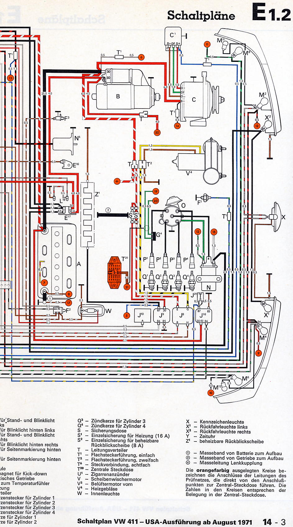 2 2 |
||
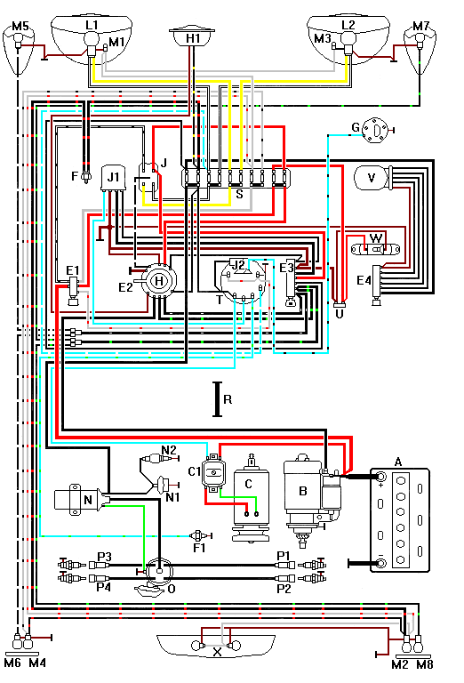
| 1973 | 412 |
 1 1  2 2 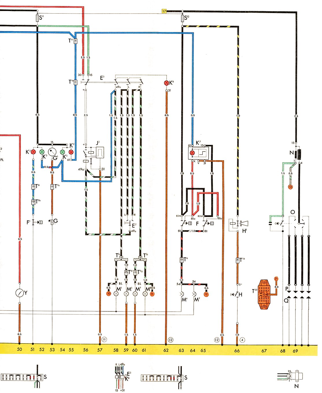 3 3 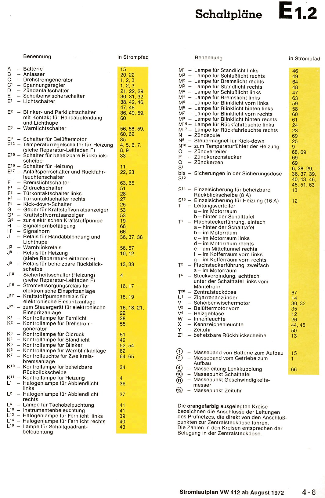 4 4 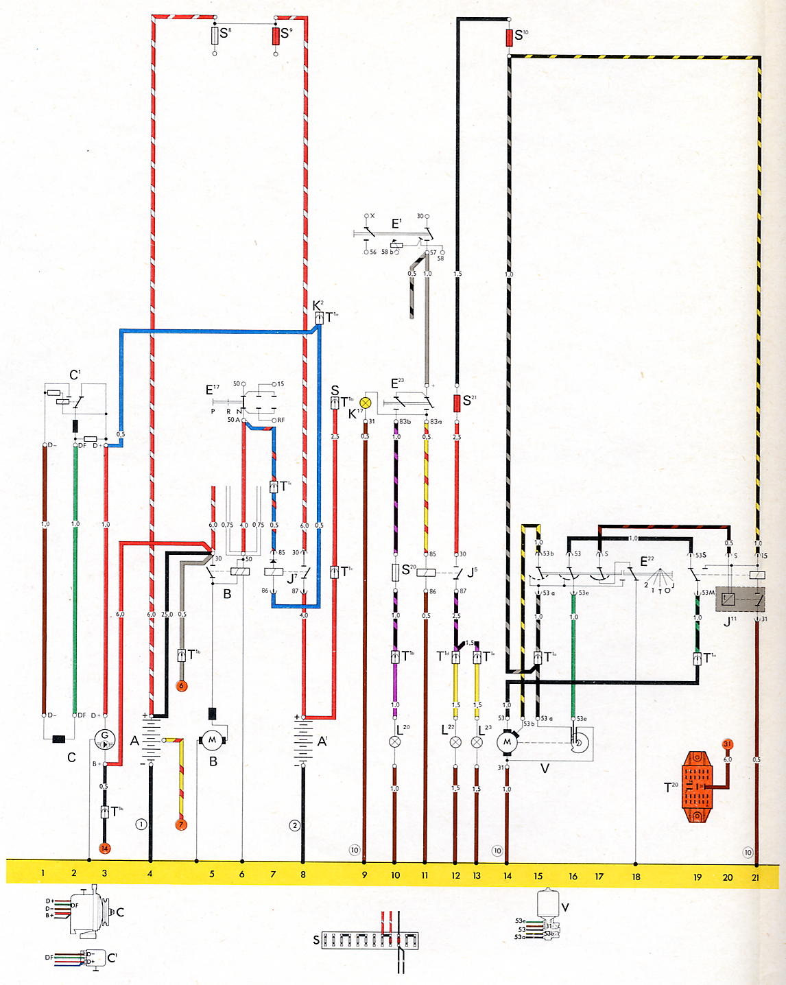 5 5  6 6 |
||
| 1973 | Type 4 USA |
 1 1  2 2  3 3 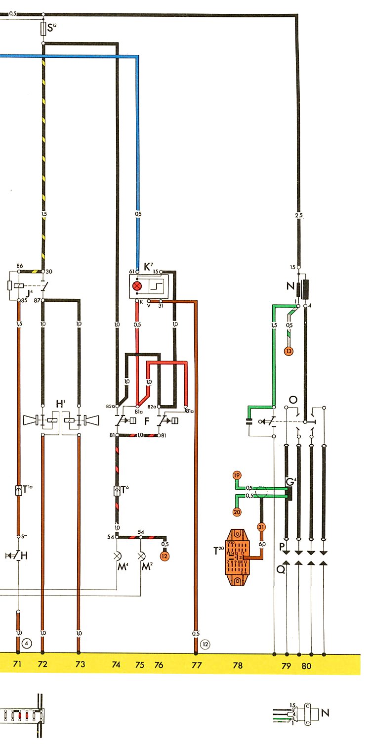 4 4 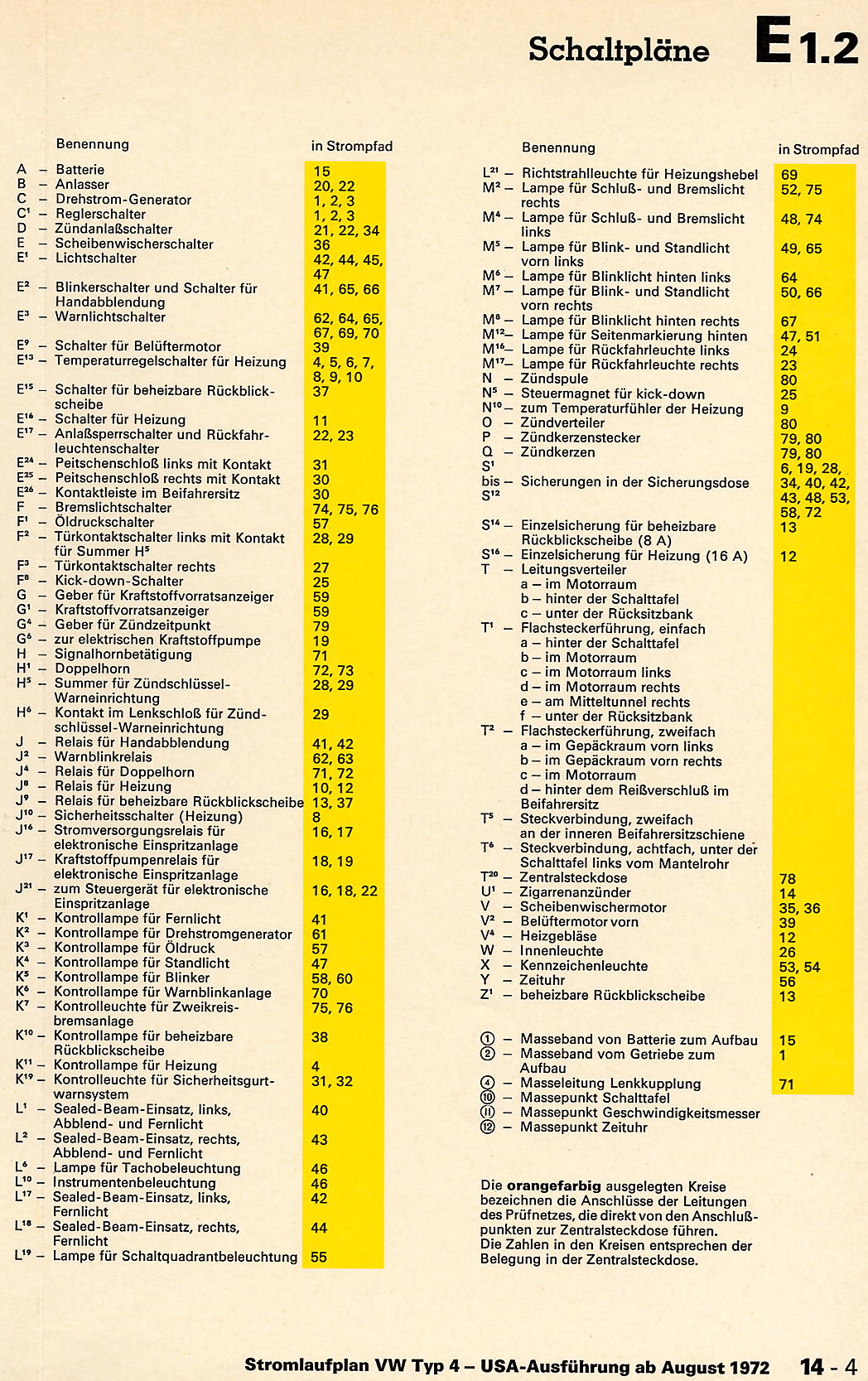 5 5 |
||
| 1974 | Type 4 USA |
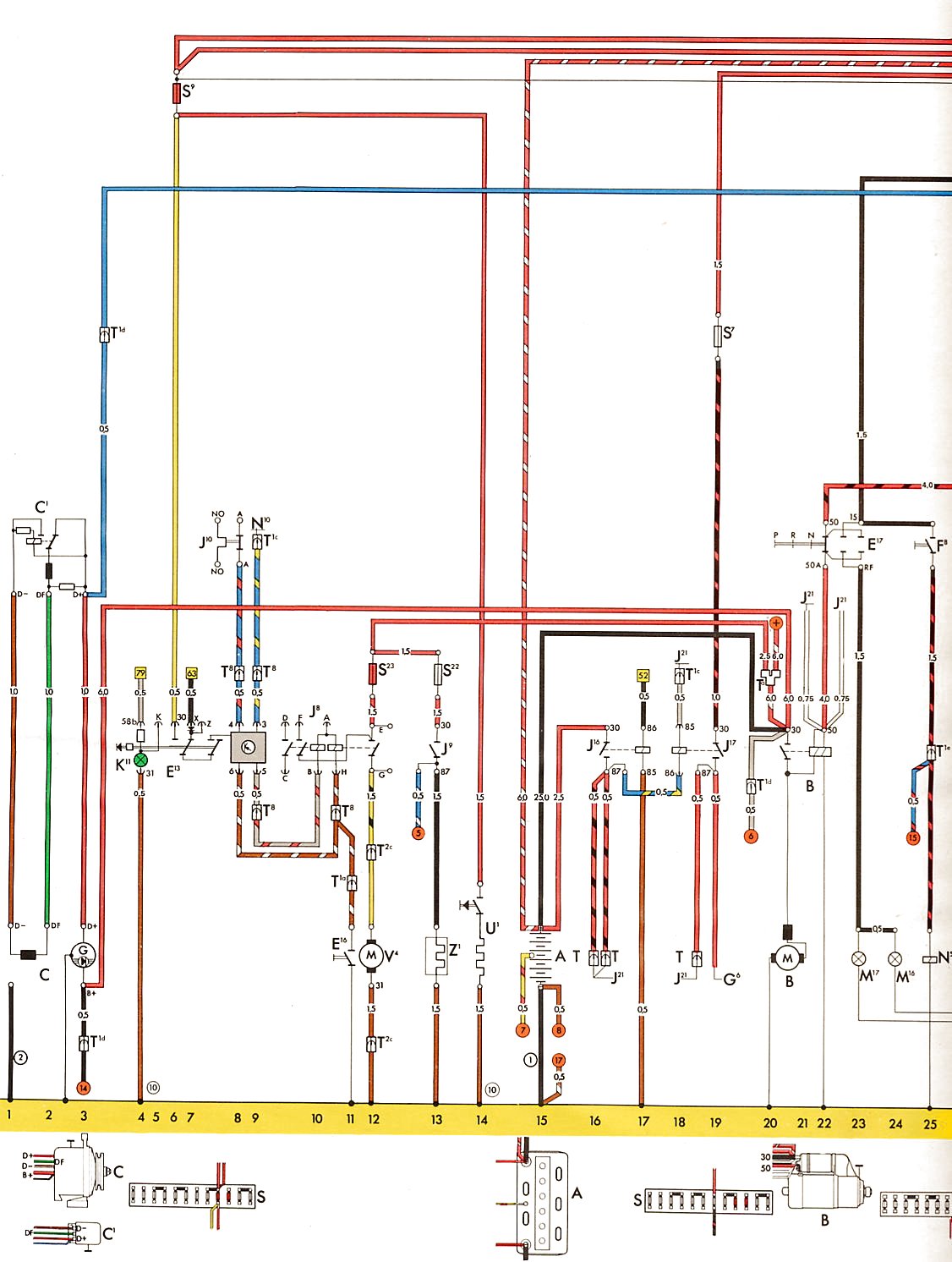 1 1 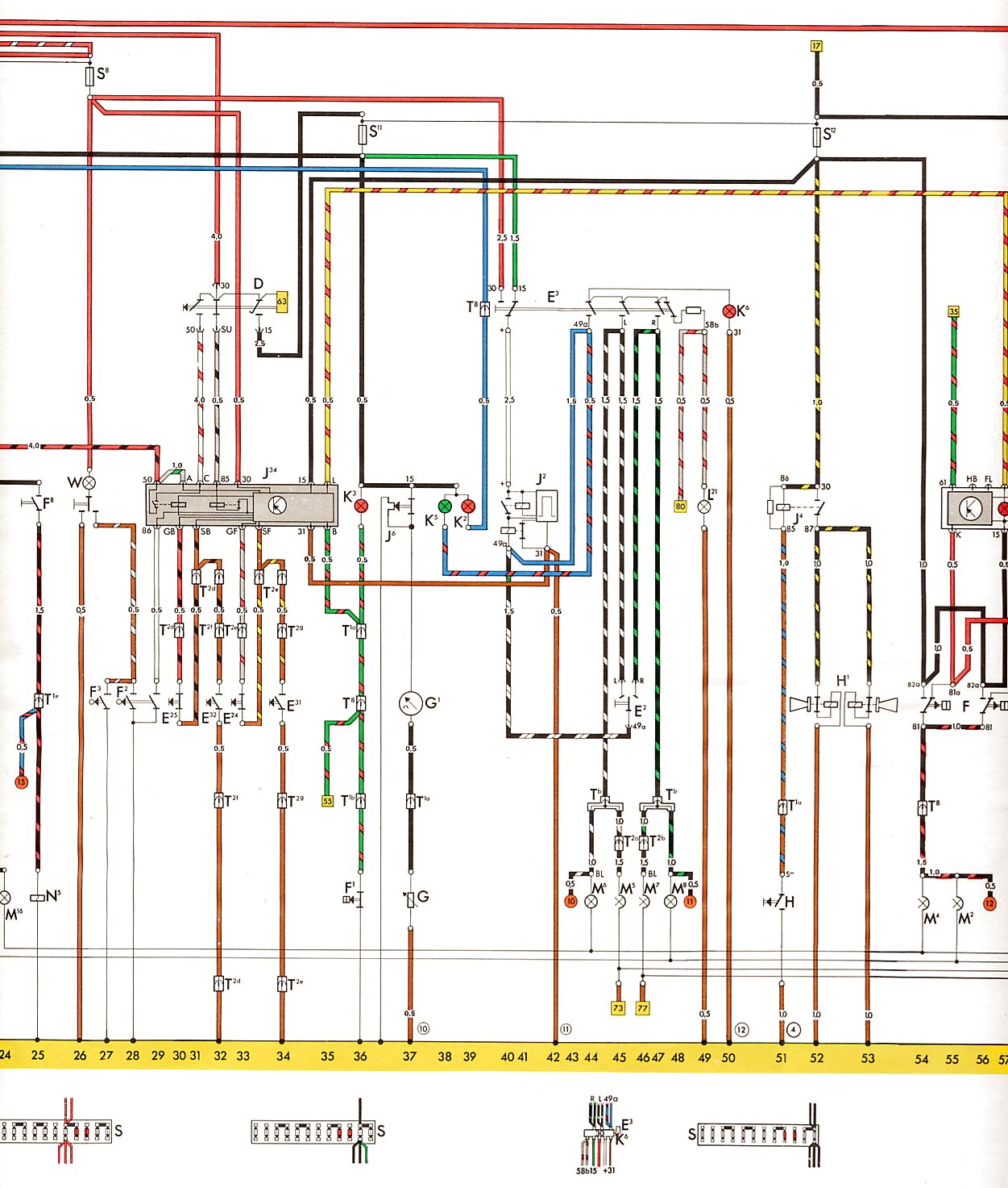 2 2  3 3 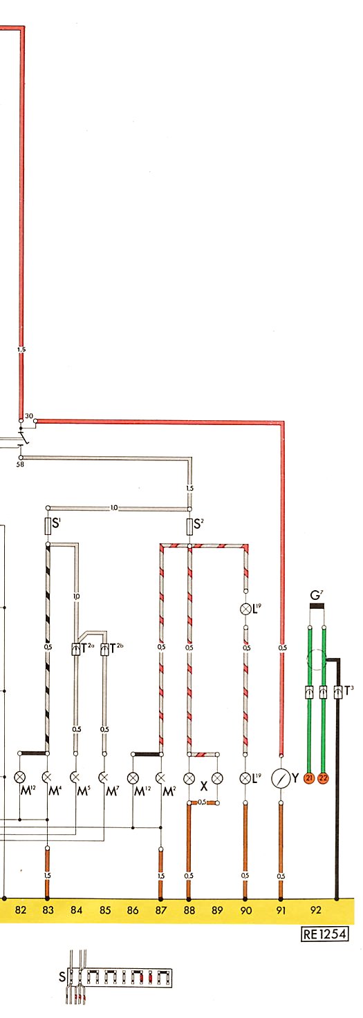 4 4 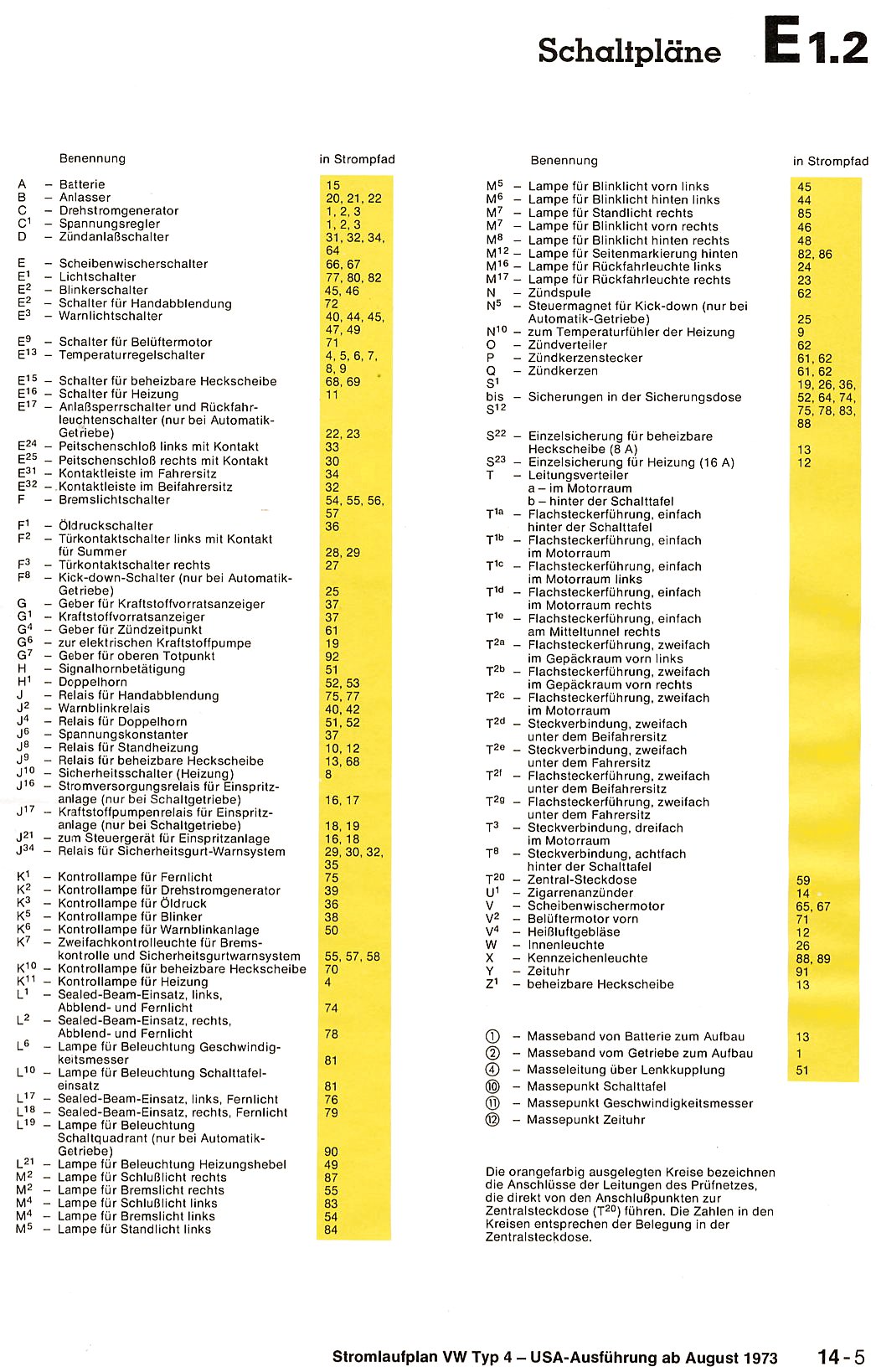 5 5 |
Type 181
| Year | Comment |
Key
|
Fuse Block
|
Diagram
|
|---|---|---|---|---|
| 1970 | 181 |
|
|
 |
| 1970 | 181 M 63 |
|
|
|
| 1972 | 181 M 63 |
|
|
|
| 1973-1974 |
|
|
 |
|
| 1974 | 181 |
|
|
 1
1 2
2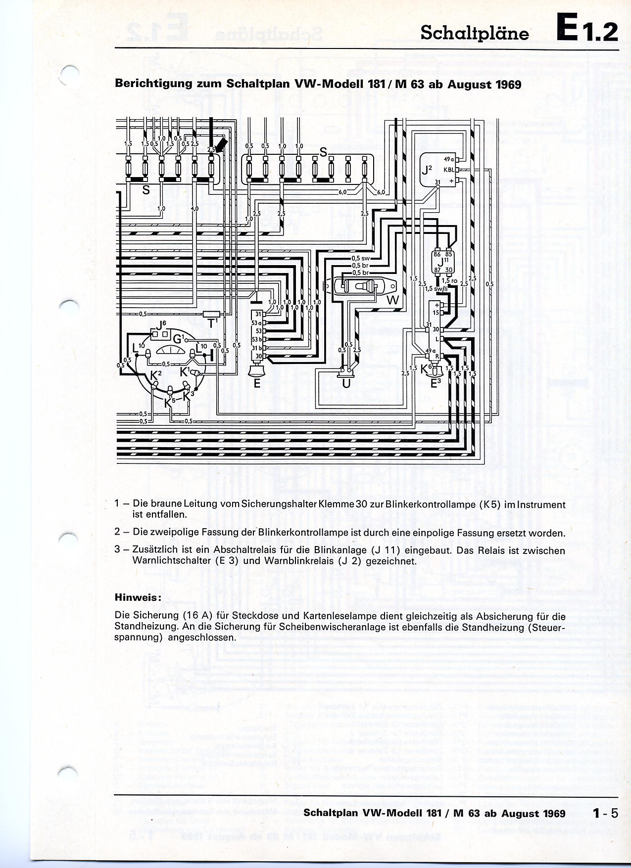 3
3 1
1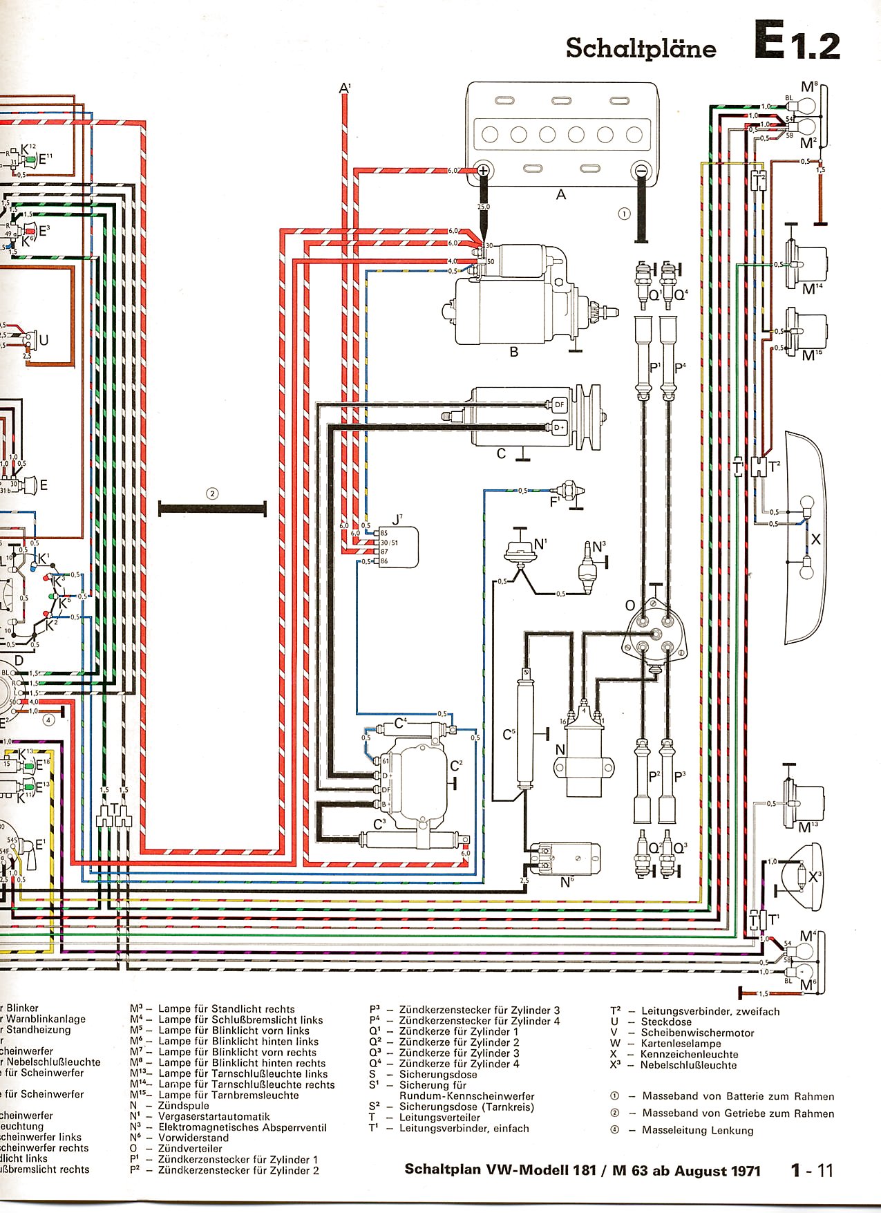 2
2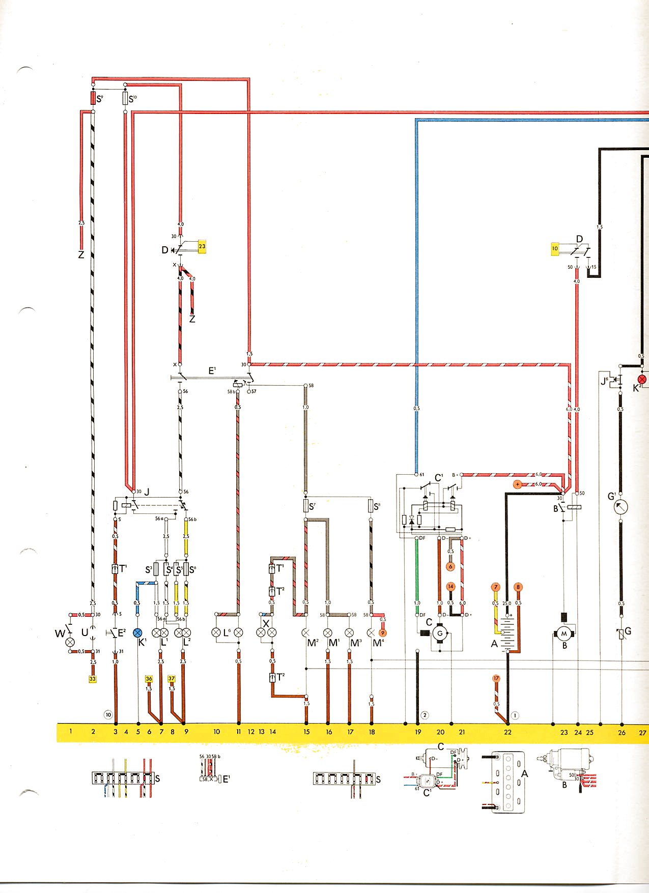 1
1 2
2 3
3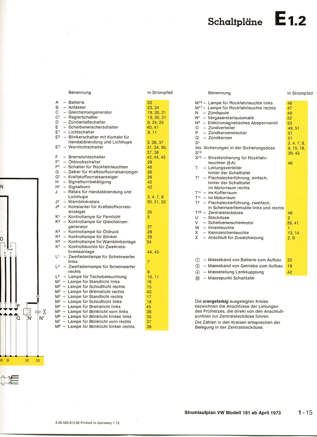 4
4Kubelwagen
| Year | Comment | Key | Fuse Block | Diagram |
|---|---|---|---|---|
| 1940-1945 |
 |
Type 48
 1
1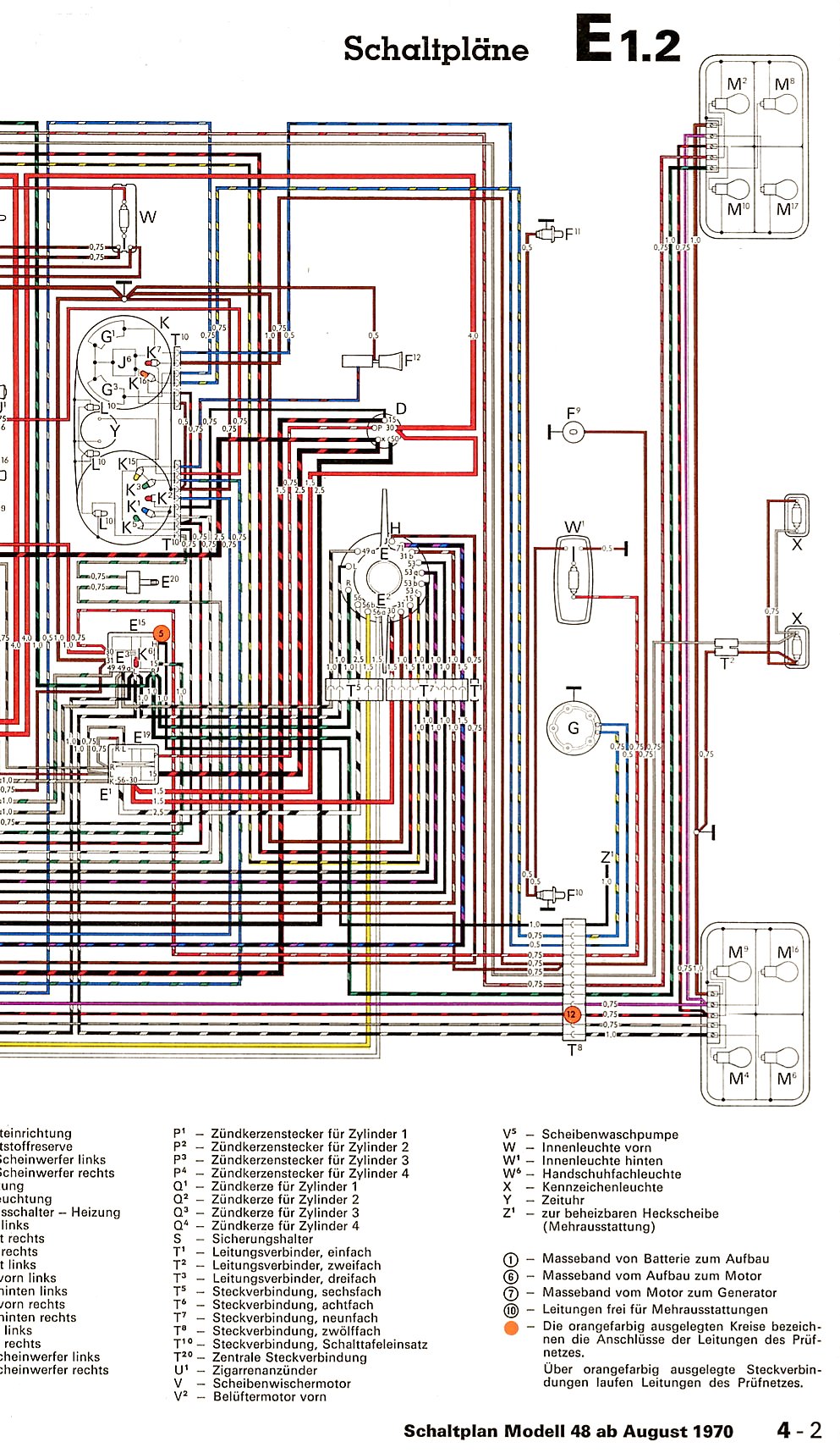 2
2 1
1 2
2 1
1 2
2 3
3 4
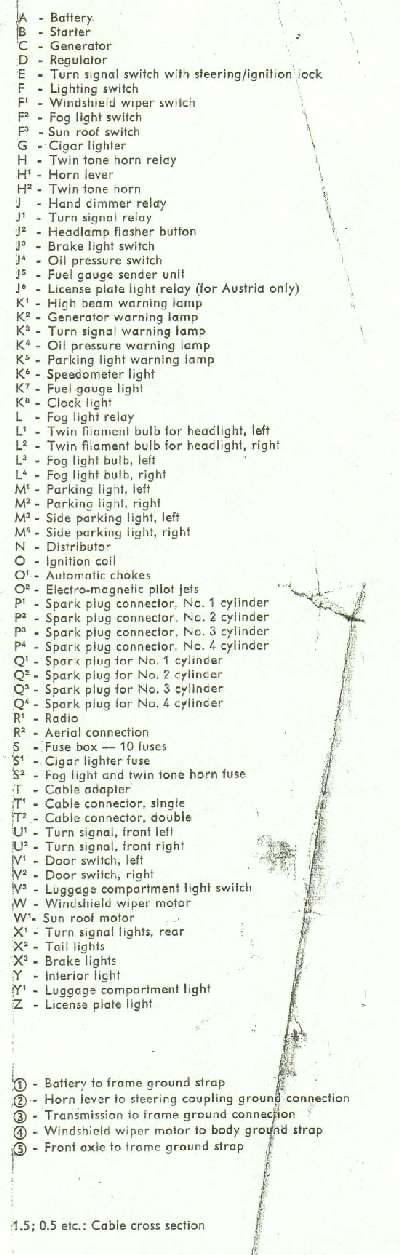
4From Bosch Automotive Handbook, 3rd edition
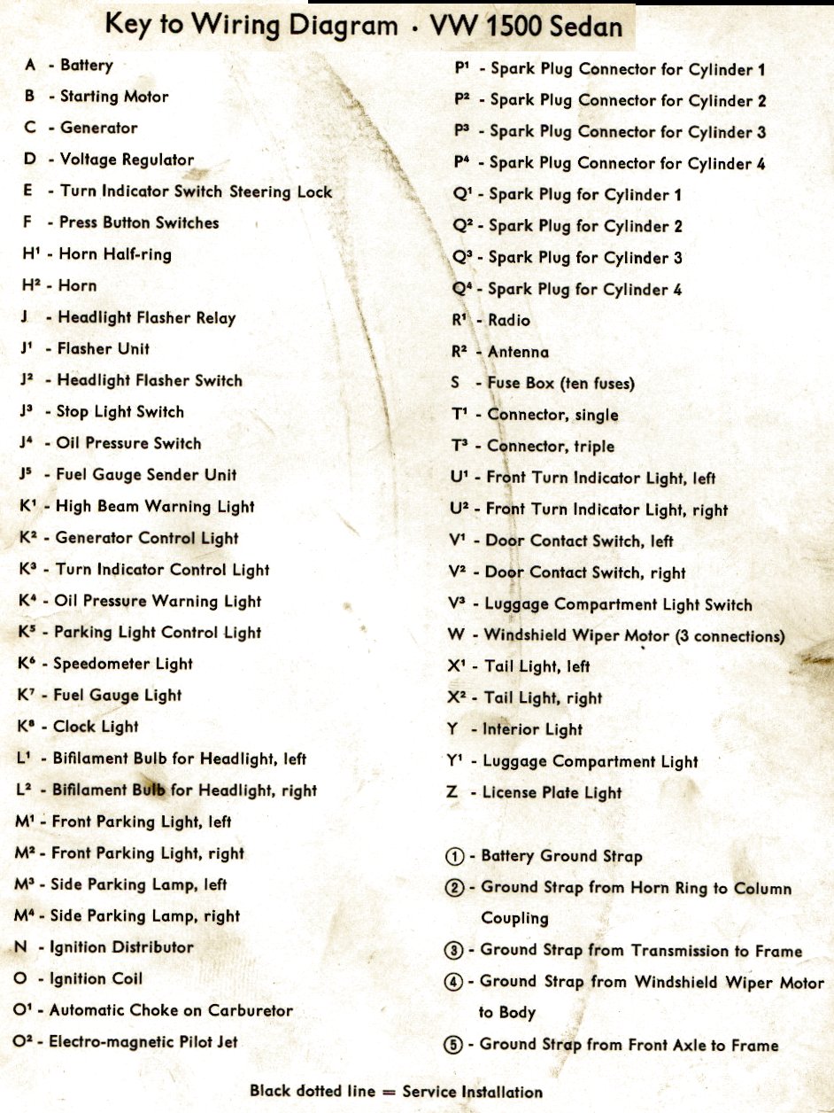
Terminal Designations (Excerpts from DIN Standard 72 552) The terminal designations do not identify the conductors, because device with different terminal designations can be connected at the two ends of each conductor. If the number of terminal designations is not sufficient (multiple-contact connections), the terminals are consecutively numbered using numbers or letters whose representations of specific functions are not standardized.
| Terminal | Definition |
|---|---|
| IGNITION | |
| 1 | Ignition coil, ignition distributor, low voltage |
| Ignition distributor with two separate electrical circuits | |
| 1a | to ignition contact breaker I |
| 1b | to ignition contact breaker II |
| 2 | short-circuit terminal (magneto ignition) |
| 4 | Ignition coil, ignition distributor, high voltage |
| Ignition distributor with two separate electrical circuits | |
| 4a | from ignition coil I, terminal 4 |
| 4b | from ignition coil II, terminal 4 |
| 15 |
Switched + downstream of battery (output of ignition/driving switch) |
| 15a | Output at dropping resistor to ignition coil and starter |
| GLOW PLUG AND STARTER SWITCH | |
| 17 | Start |
| 19 | Preheat |
| BATTERY | |
| 30 | input from + battery terminal, direct |
| 30a |
input from + terminal of battery II (12/24 V series-parallel battery switch) |
| 31 | Return line to battery - battery terminal or ground, direct |
| 31b |
Return ine to negative battery terminal or ground, via switch or relay (switched negative) |
| (12/24 V series-parallel battery) | |
| 31a | Return line to - terminal of battery II |
| 31c | Return line to - terminal of battery I |
| ELECTRIC MOTORS | |
| 32 |
Return line (Polarity reversal possible at terminals 32-33) |
| 33 |
Main terminal connection (Polarity reversal possible at terminals 32-33) |
| 33a | Self-parking switch-off |
| 33b | Shunt field |
| 33f | For second lower-speed range |
| 33g | For third lower-speed range |
| 33h | For fourth lower-speed range |
| 33L | Counterclockwise rotation |
| 33R | Clockwise rotation |
| STARTER | |
| 45 | Separate starter relay output; starter input (main current) |
| 45a |
Output, starter I Input, starters I and II (Two-starter parallel operation) |
| 45b | Output, starter II (Two-starter parallel operation) |
| 48 | Terminal on starter and on start-repeating relay for monitoring starting procedure |
| TURN SIGNAL FLASHER | |
| 49 | Input |
| 49a | Output |
| 49b | Output, second turn-signal circuit |
| 49c | Output, third turn-signal circuit |
| STARTER | |
| 50 | Starter control (direct) |
| 50a |
Output for starter control (Series-parallel battery switch) |
| 50b | Starter control with parallel operation of two starters with sequential control |
| 50c |
Input at starting relay for starter I (Starting relay for sequential control of the engagement current during parallel operation of two starters) |
| 50d |
Input at starting relay for starter I (Starting relay for sequential control of the engagement current during parallel operation of two starters) |
| 50e | Input, Start-locking relay |
| 50f | Output, Start-locking relay |
| 50g | Input, Start-repeating relay |
| 50h | Output, Start-repeating relay |
| ALTERNATOR | |
| 51 | DC voltage at rectifier |
| 51e | DC voltage at rectifier with choke coil for daytime driving |
| TRAILER SIGNALS | |
| 52 | Signals from trailer to towing vehicle, general |
| WIPER MOTOR | |
| 53 | Wiper motor, input (+) |
| 53a | Wiper (+), self-parking switch-off |
| 53b | Wiper (shunt winding) |
| 53c | Electric windshield-washer pump |
| 53e | Wiper (brake winding) |
| 53i | Wiper motor with permanent magnet and third brush (for higher speed) |
| TRAILER SIGNAL | |
| 54 | For lamp combinations and trailer plug connections |
| TRAILER STOP LAMP | |
| 54g | Pneumatic valve for additional retarding brake, electromagnetically actuated |
| LIGHTING | |
| 55 | Fog lamps |
| 56 | Headlamp |
| 56a | High beam, high-beam indicator lamp |
| 56b | Low beam |
| 56d | Headlamp-flasher contact |
| 57 | Side-marker lamp: motorcycles, mopeds. Abroad also cars, trucks, etc. |
| 57a | Parking lamp |
| 57L | Parking lamp, left |
| 57R | Parking lamp, right |
| 58 | Side-marker lamps, tail lamps, license-plate lamps and instrument-panel lamps |
| 58b | Tail-lamp changeover for single-axle tractors |
| 58c | Trailer plug-and-receptacle assembly for single-conductor tail-lamp cable with fuse in trailer |
| 58d | Variable-intensity instrument-panel lamp, tail-lamp and side-marker lamp |
| 58L | Side-marker lamp, left |
| 58R | Side-marker lamp, right; license-plate lamp |
| ALTERNATOR (magneto, generator) | |
| 59 | AC voltage, output, rectifier, input |
| 59a | Charging armature, output |
| 59b | Tail-lamp armature, output |
| 59c | Stop-lamp armature, output |
| 61 | Alternator charge-indicator lamp |
| TONE-SEQUENCE CONTROL DEVICE | |
| 71 | Input |
| 71a | Output to horns 1 & 2, low |
| 71b | Output to horns 1 & 2, high |
| 72 | Alarm switch (rotating beacon) |
| INTERIOR | |
| 75 | Radio, cigarette lighter |
| 76 | Speaker |
| 77 | Door-valve control |
| SWITCHES | |
| Break-contact and changeover switches | |
| 81 | Input |
| 81a | 1st output, break side |
| 81b | 2nd output, break side |
| Make-contact switches | |
| 82 | Input |
| 82a | 1st output |
| 82b | 2nd output |
| 82z | 1st input |
| 82y | 2nd input |
| Multiple-position switches | |
| 83 | Input |
| 83a | Output, position 1 |
| 83b | Output, position 2 |
| 83L | Output, left-hand position |
| 83R | Output, right-hand position |
| CURRENT RELAY | |
| 84 | Input, actuator and relay contact |
| 84a | Output, actuator |
| 84b | Output, relay contact |
| SWITCHING RELAY | |
| 85 | Output, actuator (end of winding to ground or negative) |
| 86 | Start of winding |
| 86a | Start of winding or 1st winding |
| 86b | Winding tap or 2nd winding |
| Relay contact for break and changeover contacts | |
| 87 | Input |
| 87a | 1st output (break side) |
| 87b | 2nd output |
| 87c | 3rd output |
| 87z | 1st input |
| 87y | 2nd input |
| 87x | 3rd input |
| Relay contact for make contact | |
| 88 | Input |
| Relay contact for make and changeover contacts (make side) | |
| 88a | 1st output |
| 88b | 2nd output |
| 88c | 3rd output |
| Relay contact for make contact | |
| 88z | 1st input |
| 88y | 2nd input |
| 88x | 3rd input |
|
ALTERNATOR and VOLTAGE REGULATOR GENERATOR and GENERATOR REGULATOR |
|
| B+ | Battery positive |
| B- | Battery negative |
| D+ | Dynamo postive |
| D- | Dynamo negative |
| DF | Dynamo field |
| DF1 | Dynamo field 1 |
| DF2 | Dynamo field 2 |
| Alternator with separate rectifier | |
| J | Excitation winding positive |
| K | Excitation winding negative |
| Mp | Center point terminal |
| U,V,W | Alternator terminals |
| DIRECTION INDICATOR (turn-signal flasher) | |
| C | First indicator lamp |
| C0 | Main terminal connection for separate indicator circuits actuated by the turn-signal switch |
| C2 | Second indicator lamp |
| C3 | Third indicator lamp (e.g., when towing two trailers) |
| L | Turn-signal lamps, left |
| R | Turn-signal lamps, right |
Cross-reference for old and new terminal designations in accordance with DIN 72 552. Only terminal designations whose significance has altered are given.
| OLD | NEW |
|---|---|
| 1 | 1, 53(wiper), 53e |
| 2 | 2, 53e |
| 3 | 53, 53b(wiper) |
| 4 | 4, 53a, 53b(wiper) |
| 15 | 15, 49(turn-signal flasher) |
| 15+ | 49 |
| 15/54 | 15, 49, 54 |
| 16 | 15a, 15 |
| 30 | 30, 33(motor) |
| 30/51 | 30, 87, 88(relay) |
| 30f | 45 |
| 30h | 45, 45a |
| 30h I | 45a |
| 30h II | 45b |
| 30L | 33L (motors) |
| 30R | 33R (motors) |
| 31 | 31, 31c, 32(motors) |
| 31a | 31a, 31c |
| 31B- | B- |
| 50 | 50, 50b, 50f, 50h |
| 50a | 50, 50a, 50e, 50g |
| 50b | 50d |
| 50k | 50d |
| 50 II | 50c |
| 51 | 51, 59, B+ |
| 51 - | 59 |
| 51a | 59 |
| 51B+ | B+ |
| 54 | 54, 53a, 54g |
| 54/15 | 15 |
| 54d | 53(wiper) |
| 54e | 33b, 53b(wiper) |
| 54L | 49a |
| 58 | 58, 58L, 58R |
| 58b | 58b, 58d |
| 59 | 59a |
| 85d | 31b(alarm switch) |
| B+30 | B+ |
| B+51 | B+ |
| D+/61 | D+ |
| D-/61 | D- |
| H | 71 |
| HL | L (L54b) |
| HR | R (R54b) |
| K | C |
| K0 | C0 |
| K1 | C, C2 |
| K2 | C2 |
| K3 | C2, C3 |
| K4 | C2, C3 |
| L54 | L (L54) |
| N | 55 |
| P | C, 57a |
| PL | 57L |
| PR | 57R |
| R | R, 75 |
| R54 | R, (R54) |
| R54b | Rb |
| S | 49a, 53(wiper) |
| S4 | 49a |
| SBL | (L54) |
| SBR | (R54) |
| VL | L |
| VR | R |
| + | 15, 49(turn-signal flasher) |
| 53, 53a(wiper) | |
| +2 | 53a |
| +15 | 49 |
| -1 (ignition coil), 31 |
Power consumption of vehicle electrical leads (average values)
| Backup lamps | 25W |
| Battery ignition | 20W |
| Blower motor | 80W |
| Cigarette lighter | 100W |
| Fog lights | 35W each |
| Fog warning lamp | 35W (red fog light on rear) |
| Glow plugs | 100W each |
| Headlamps, low beam | 55W each |
| Headlamps, high beam | 60W each |
| Heated rear window | 120W |
| Horns and fanfare horns | 25W...40W each |
| Instrument-panel lamps | 2W each |
| Interior lamp | 5W |
| License-plate lamp | 10W |
| Parking lamp | 3W...5W |
| Radio | 10W...15W |
| Side-marker lamps | 4W each |
| Starting motor for truck | 2.2kW...12kW |
| Starting motor for car | 0.8kW...3kW |
| Stop lamps | 18W each |
| Tail lamps | 5W each |
| Turn-signal lamps | 21W each |
| Vehicle heater | 20W...60W |
| Windshield wiper | 90W |